


 ,
,  ,
,  ,
,  ,
,  ,
,  ,
,  ,
, 

 ,
,  ,
,  ,
, 
 ,
, 
 ,
,  ,
,  ,
, 

 ,
,  ,
, 
 ,
, 
 ,
,  ,
,  ,
, 
 ,
,  ,
,  ,
,  ,
,  ,
, 
 ,
,  ,
, 

 ,
,  ,
,  ,
, 


 ,
,  ,
,  ,
,  ,
, 
 ,
, 
 ,
,  ,
, 
 ,
,  ,
,  ,
,  ,
,  ,
, 


 ,
,  ,
, 


 ,
, 

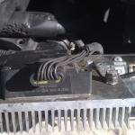
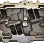
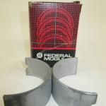
ANSWER: Cut-outs of the GM 6.5 diesel
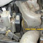
The 6.5 GM turbo diesel ECM / PCM has a lot of software issues, but the biggest frustration is the unexpected cut-offs of the engine
These can be primarily caused by the lift pump and its fuel pressure - and / or the encoder sensor - also known as the "optical sensor"
Believe it or not - the engine can unexpectedly shut down if the fuel temperature changes drastically like when you fill up with cool fuel from a station - and it reaches the IP to change the temperature fast at the sensor, it also can do the same when you start the engine and the fuel in the IP is warm from a warm engine and cool tank fuel hits it.
The engine will immediately restart easily in both these scenarios because what killed the engine is the PCM software trying to make a timing change for what it surmises is a change in fuel quality. This will usually only happen around a low idle speed - or it may misfire - or hiccup or "fish bite" as some call it and may keep running if the idle is up around 640 rpm or more.
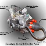
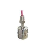
The optical/fuel temperature sensor supplies three (3) signals to PCM for fuel control and timing. A high resolution signal helps determine injection timing and fuel control. A pump cam signal provides reference pulses that monitor and help determine injection timing. The fuel temperature signal helps the PCM determine pump advance or retard requirements and fuel flow.
A Fault in the optical sensor related to wiring will produce fast idle and performance problems. Poor fuel will also produce a fast idle.
A Problem will cause high resolution circuit fault, or a cam reference pulse error fault.
Fuel Temperature Sensor Description and Operation
The fuel temperature sensor is part of the optical sensor. It is a thermistor that controls signal voltage to the PCM. Voltage from the sensor will vary inversely to fuel temperature (i.e. high temperature equals low voltage; low temperature equals high voltage).
The PCM provides a reference signal to the fuel temperature sensor. As fuel temperature changes, the sensor will alter the strength of the voltage. Through monitoring, the PCM knows fuel temperature and will take this into consideration when determining fuel delivery rates. Fuel temperature also normally relates to fuel viscosity, which can affect fuel delivery rates. This is what can cause unexpected shutdowns that restart easily when it is only a temperature issue of the tank versus the IP
Allowable fuel temperature range is 50 deg F to 194 deg F when running - and this is also affected by low lubricity fuel because the IP is immersion lubricated by also the fuel pressure to the IP inlet which also serves as IP lubrication "oil pressure". That why fuel inlet pressure also must be at least 5 psi
You can get a rough idle because of the high pop marine application fuel injectors which can cause derivability issues and for a Diesel feels and sounds like a big cam type lope due to ignition delay because of - yes too much fuel - and is often misdiagnosed as a bad optical sensor.
Another issue is when owners put on a manual waste gate controller going from factory vacuum controlled boost to a mechanical boost controller the vendors fail to notice that the boost solenoid must remain in the circuit to the ECM and in good working order or you will never be able to reset top dead center offset TDCO on OBD-2 6.5 TD
That is not the only thing those manual waste gate controllers cause problems of. The best thing is never put on that manual waste gate controller - or put the vacuum operated system back on.
Here is a symptomatic scenario to a failing "optical sensor"
trouble with running and starting - engine may "hiccup" while running, (Some people call it "fish-biting") sometimes... and will get to the point where it will not start easily. Extended cranking may be needed to start it - and you may run the batteries down before it does start. it will run terribly for quite a while before gradually becoming smoother as it warms up to operating temperature.
Most mechanics or dealers (if you can find on to even look at a 6.5) will say "it needs a new injector pump". It may or may not throw an optical sensor DTC.
Most mechanics will say they can't change the sensor, but it is possible to change the Optical / Encoder sensor itself - and it entails only removing the IP top cover - HOWEVER - you cannot change the encoder sensor wheel that spins through it - without disassembling the IP to rebuild it - which actually should not be damaged anyway and is re-useable even in a re-build.
Remember the encoder sensor provides three functions - so replacing it alone may solve a lot of issues.
Here is a post of a classic dying or weak lift pump. We use this post becasue it is an completely unaltered "stock" 6.5
""Hi ALL
I have a problem with a 2001 GMC minibus with a 6.5 It started about a week ago I was driving along and it died just as if you shut the key off. Coasted to a stop and it started just like normal Then a few miles down the road did it again. then ran fine for about 50 miles then it will do it again. Then every so often it will just glitch and then it stays running finally tonight it did it about 10 times in a 14 mile 1 way trip I dropped kids off in the town and run fine. Got back on the highway started doing it again and then every time started getting harder to start and finally we had to tow it home.I have not done anything yet other then changed fuel filter on Monday hoping that would be causing it. Not so It really does not feel like fuel filter there is no studder no loss of power its just dead. Has anyone had this same problem. I really have no idea where to start on this one could it be a fuel shut off solenoid or something like that. I have never been around the 6.5 diesel before we bought this bus used this year. First Baby bus we have owned.
Any help would be great
THANKS ""
This is the classic weak lift pump scenario that pumps when first turned on and then gets weak while running - and the classic tell-tale is the highway trip - which causes a steady need of volume and pressure of fuel - and obviously the lift pump just could not deliver it.
By the way this post was never answered as solved from 2007
6.5 engine design
The 6.5 is a pre-chamber diesel. Also called "indirect injection" These engines are "cetane sensitive" and the 6.5 needs ideally 44 cetane or better to run properly. they are quieter engines, but because the fuel is injected in to a small confined chamber - it needs to ignite quickly and fully immediately. Thus the higher cetane need. The advantage is that as opposed to direct injection, the ignition of the fuel does not slam shut the valves which is what contributes to the diesel engine engine characteristic clatter and rap rap rap noise.
Daimler-Benz was the leader in this technology
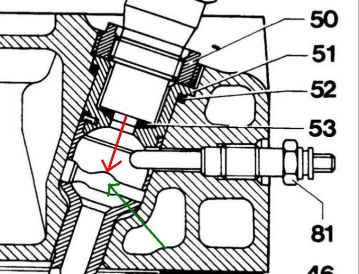
A typical prechamber design above
Rudolf Diesel did not live to see the advent of his invention in the motor vehicle, but he did foresee the use of the diesel engine in vehicles. “I am firmly convinced,” he wrote in 1913, the year of his death, “that the automotive engine will come, and I will then consider my lifework to be complete.” Though the brilliant design engineer Prosper L’O range had already developed the prechamber combustion principle for Benz & Cie. by that time, it was to take more than ten additional years until a truck diesel based on it would reach the stage where it was ready for production.
You can read more at http://media.daimler.com/marsMediaSite/en/instance/ko/1923-Go-ahead-for…
Indirect injection, or IDI diesels, were much more common in the 80's and early 90's, but have been altogether replaced by more efficient direct injection, or DI engines. The names can be misleading, as the difference between the two engines is not in how fuel is injected, but rather where it is in injected. IDI and DI engines have different combustion chamber designs, the later having a more traditional design while the IDI has a "pre-chamber" in which fuel is injected into before traveling into the actual combustion chamber. All versions of the Power Stroke, Cummins, and Duramax diesel models are direct injection diesels, where as International's earlier 6.9L/7.3L and General Motor's 6.2L/6.5L motors had pre-chambers and therefore fall under the category of IDI's.
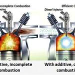
The pre-chamber design was great when fuel quality was above 44 Cetane at the pump and mechanical injection was a simple affair, but today the electronic injection systems like the DS-4 and poor fuel make the pre-chamber design somewhat of a liability and today fuel cetane is 38 to 40 average in the US.
The biggest thing happening is the low cetane which results in less than ideal combustion in a pre-chamber diesel and the enclosed space tends to back foul the injectors if the injection pressure is not sufficiently high and the fuel willnot ignote quickly cleanly and immediately. A sad reality is the DS-4 will "weak" inject if starved for fuel and has initially low inlet pressure.
The DS-4 IP woks by multiplying the pressure it is fed at its inlet and is internally regulated to keep a steady pressure of around 5 psi if fed anything between 5 and 14 psi. If not fed good fuel at a good pressure - the pre chamber can actually foul up and fill up with carbon along with the injector nozzles and then the engine will bang like a rod spun a bearing.
Owners have changed injectors only to find - the problem is not solved - because the pre-chamber is actually packed with carbon from the poor fuel thy have been burning - and usually do not know it. Once carbon forms it cannot be dissolved easily even chemically - it may break into chunks and break "loose" but you cannot eject it away and out an exhaust valve - the only way is to manually disassemble the engine and scrape it out. Let us not mention even if you send it out the exhaust valve - will it hit the turbo wheel and take a chunk out of on the way ??
Effectively if the prechamber plugs up, there is a small injection path hole down the middle and you are left with a real crappy noisy direct injection scenario. Thankfully that is a rare worse case scanario
"Rebuilt" injectors consist of NEW injector nozzles which fill with carbon - and usually todays ULSD fuel - of which the low lubricity nature of the fuel can also contribute to "eroding" the nozzle injection pintle area due to the high pressure spraying through the pintle area cause friction which also creates heat - is another good reason to increase the lubricity of the fuel as much as possible. In these injectors it literally takes 2 minutes to "rebuild" an injector with a replacement nozzle.
Cylinder heads have been removed from 6.5 engines and the pre chamber is basically nonexistent packed with carbon. Thus proper lift pump pressure is critical and good fuel - or today use of a "great" fuel additive that can push cetane above 44 is imperative to good 6.5 operation.
IDI VS. DI
IDI - Indirect Injection Diesel
IDI diesel engines utilize a pre-combustion chamber, typically referred to as a swirl chamber or prechamber. Fuel is injected into the prechamber where it rapidly mixes with air and autoignition occurs. As the flame front expands in the pre-chamber, it forces fuel to enter the combustion chamber rapidly, effectively mixing the fuel with air in the cylinder and atomization is achieved. The glow plug is also located in the prechamber, and the shape of the pistons in an IDI tend to resemble those of a gasoline engine.
DI - Direct Injection Diesel
DI diesel engines inject fuel directly into the combustion chamber, right into the top of the piston. The pistons on a DI engine typically have a bowl or cup machined into them that the fuel is directed into. DI engines operate at higher injection pressures and therefore more complete atomization occurs, meaning these engines do not require a prechamber to ensure proper diffusion of the fuel into the air.
IDI engines are now a thing of the past, as the direct injection diesel operates at a much higher efficiency with significantly lower emissions and greater performance. That, however, does not mean that used models have lost their luster. IDI engines of the 80's and 90's lack modern sophistication and are therefore relatively easy and inexpensive to maintain. The lack of electronics and emission controls tends to contribute to greater reliability in IDI engines, as the system is far less complex. Furthermore, IDI equipped pickups can usually be purchased for cheap on the used market. Despite the attractiveness of older IDI diesels, direct injection diesel engines tend to have the following advantages over a comparable IDI counterpart:
• Higher thermal efficiency
• Lower NOx and particulate (soot) emissions
• Lower Noise, vibration, and harshness (NVH)
• Greater performance potential
• Greater high altitude performance (compared to naturally aspirated IDI engines)
BUT . . .a DI engine - even with electronic common rail injection - is always noiser than a prechamber engine running - if you really care
This below from http://www.10000cows.com/stanadyne-ds4.htm
Why does the 6.5L have so many problems? People tend to blame electronics (or the EPA) but there has not been a highway truck built since the late 1980's without electronic engine management. The well-loved Detroit series 40, 50, and 60 are all electronically controlled - the engines were designed that way. Even the last V92 family received electronic fuel injection. The Cat 3406, Cummins ISX, (and ISL, ISC, and ISB), Powerstroke, and DT466E - these are engines that last a million miles between rebuilds, and all electronically controlled. You can breathe the air thanks to all of this technology. You want to see what happens when you don't do this? Go visit India and China and Russia. Visit a bus barn in Hungary or Brazil full of Rabas or 'Old Smoky' Mercedes OM352. So what went wrong? Let's look at what we are working with....
The 1994-1995 6.5L TD ECM consists of a fairly low-tech set of chips. The main processor is a 68HC11F1 running with a 12.59 MHz crystal. There's about 48k of code and calibration space available. A Delphi IOR chip supplies 240 bytes of RAM and also some I/O ports and four PWM channels. A configurable timer chip is used to process pulses from the diesel pump's optical encoder and also the CKP signal. Not a big problem except that the people writing the software screwed up a bit. There are a few bugs in the software. The ones I have found include:
- The software filter used to prevent ECTS-based tables from chattering with sensor noise is not functional. There is supposed to be a deadband of 2 degrees C, however, that deadband comparison is screwed up because of a missing # sign in a CMPB instruction in the source code. Something of note is that the OBD-II version of the software does not correct this.
- A flag fetch from calibration does not get the correct mask. The problem here is a missing # sign in a BIT instruction in the source code. There are a couple of cases of this. One of them may actually cause a fuel dropout in the case of certain unrelated DTC's setting. It looks like that part of the code was rewritten for the OBD-II version.
- The SCI interrupt is not equipped to be interrupted by the CKP, CMP, VSS, or OSS interrupts. That would be fine if the interrupt just stored the appropriate data and called the main program loop to actually form an SCI message. But it doesn't. So what happens is you miss interrupts if you have a scan tool connected. The correct solution would have been to disable the 160 Hz interrupt, disable the SCI interrupt, re-enable global interrupts, format the outgoing data stream, disable global interrupts, re-enable the SCI interrupt, re-enable the 160 Hz interrupt, then return from SCI interrupt. The OBD-II version checks during long interrupt-disabled conditions now so this is not a problem any more.
- The subroutine used to calculate the desired EGR pressure is called twice in a row. This was corrected in the OBD-II version of the code.
- In several spots, a double-precision arithmetic operation (subd, addd) only loads half of the input, leaving the other register containing some random stuff.
- In several spots, engine speed (and sometimes other things - but engine speed happens multiple times) is calculated, then is just thrown away.
Other than that, the ECM probably will do its job, more-or-less all of the time. Automotive ECM's have been shown to be rather reliable and there's no particular reason to think this one has a big problem.
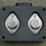
The pump driver module has a reputation of blowing up. Yea, probably it deserves it. To start with, it appears to use a couple of huge bipolar transistors configured as a high-side switch, and also as a linear current regulator. I don't think I would do it that way. Using MOSFETs to switch the solenoid valve along with a high-speed PWM current regulator would be a much better solution IMHO. The Cummins ISC system, which uses a similar pump control solenoid, uses PWM control. The current trace is a straightforward linear 12A current limit. That would make a peak power dissipation (not including clamping) of around 100 watts. Thismight be interesting for someone who is circuit-minded.
The optical sensor has issues. It is bathed in diesel fuel, and is at the mercy of whatever is in there. Air bubbles? Funny thing is that Bosch has a VP44 pump with an optical encoder, as well, and it does not have a bad reputation. Does an 8-cylinder VP44 pump exist? Perhaps a good retrofit kit would be a VP44 and a new ECM.
The diesel pump. It is a solenoid-controlled rotary pump. There are several ways of modulating fuel and timing in an electronically controlled diesel pump. They are...
- Sliding rotor (EPIC). This limits plunger travel mechanically, using hydraulic pressure. The ECM controls the pressure using a pair of solenoid valves.
- Mechanical start-of-injection, solenoid spill (Lucas, Stanadyne DS4 in pump-spill mode). Start-of-injection is mechanical so the stresses on the pump are only huge. End-of-injection has some pretty substantial forces associated with it.
- In-line sleeve pump with prestroke control. Injection quantity is controlled via fuel rack, start-of-injection is controlled by timing rack. Based on the old Bosch inline pump, used on John Deere tractors, and a Zexel version is used on some older Isuzu trucks.
- Control collar (Bosch VP37). This controls fuel quantity usually via fuel throttling (cavitation of the pump) or stroke control. Timing is controlled via servo-controlled timing piston, similar to mechanical pumps. Injection timing must be measured with an electromagnetic injector.
- Solenoid SOI, solenoid spill (Bosch VP30, VP44, Stanadyne DS4 in spill-pump-spill mode). Most flexible until we get to common rail (Duramax).
- Brute Force Electronic Unit Injector, spill-pump-spill.
- Diesel timed injector. Uses liquid plunger made with diesel fuel to vary plunger length and injection timing, Cummins ISX.
- Common rail or distributor brute-force injection. Uses a solenoid valve as in a straightforward metering system (very much like a gasoline fuel injector). Duramax, Cummins ISC, Smart ForTwo CDI.
The design requirements for solenoid spill are substantial. Stanadyne didn't get one or two of them right. Things that they might have got not-quite-right:
- Slope of cam too aggressive (desired pressure or pumping rate too high) for materials.
- Pump cavitation is causing an issue.
- Resonances in the pump causing multiplication of forces beyond expected values.
- The pump appears to rely on centrifugal force to pull the plungers out - the whole case seems to be pressurized about equally. I think that is a function of the fill/spill solenoid arrangement. If the inlet of the injection pump is at a significantly higher pressure than the rest of the pump, more solid operation should be assured. I'm not 100% sure on this but the pumping plunger assembly looks a bit suspect to me. I'd probably want to get a dead pump and disassemble it to figure out if this would be an issue or not, perhaps my understanding of the internal plumbing and case pressure control is flawed.
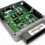
16183977 ECM (1994-1995)
Here is a photo of the guts of the 1994 to 1995 ECM. I have never seen a photo of this ECM's guts, so I took the liberty of making this one. I think a lot of people get lost from here down, but what follows is something that any ECM hacker probably could figure out with a meter and the ECM in front of them.
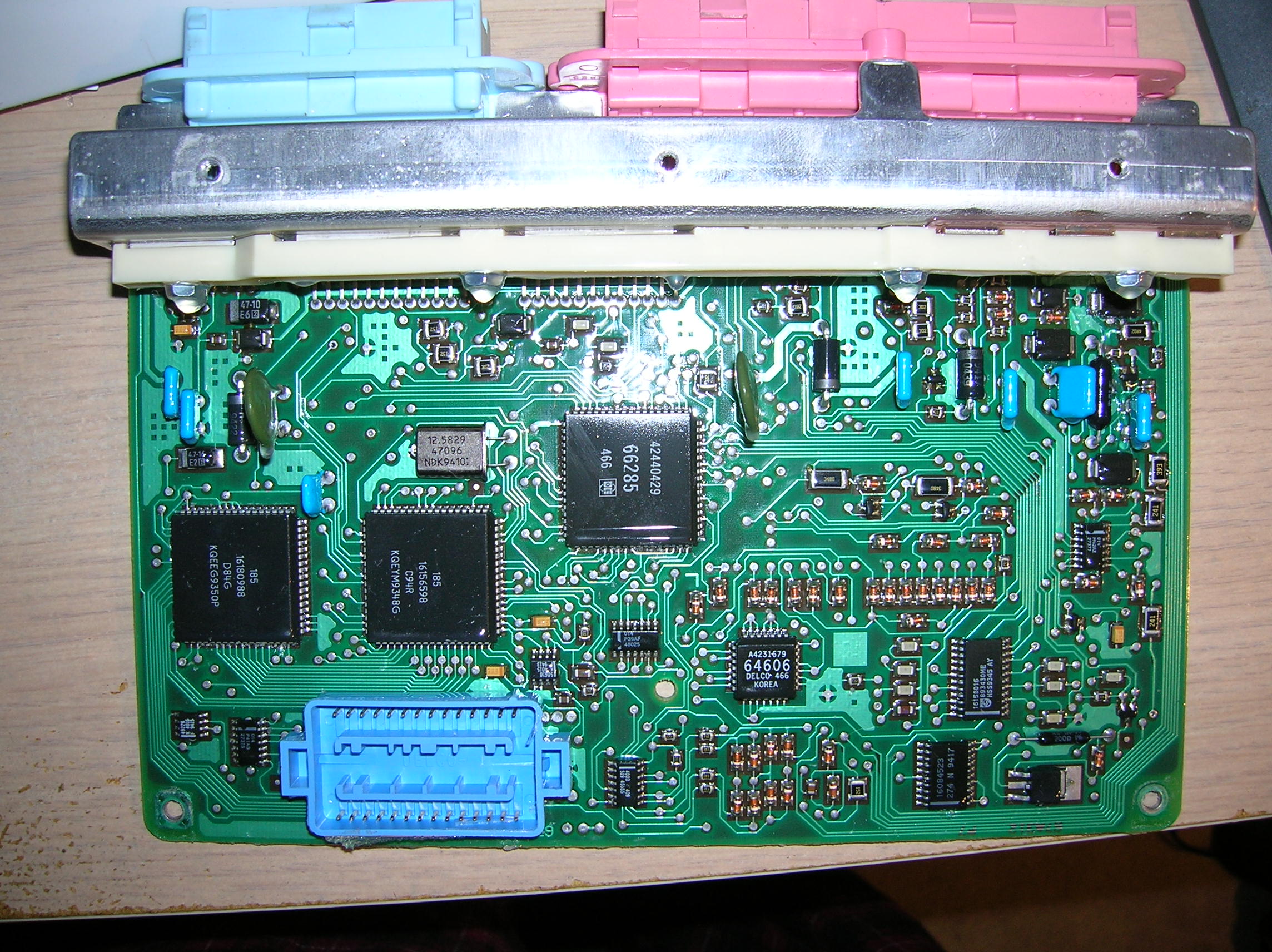
Parts on the board of note:
- 16055199 = voltage regulator
- 16166240 = quad driver module with diagnostics
- 16034993 = stepper motor driver
- 16064606 = serial output driver
- 16084523 = SO-20 VR sensor amplifier for transmission input shaft speed
- 16158016 = 74HC4067 analogue mux
- 45555 = LM339 comparator
- 48025 = SO-14 quad NAND gate, 74HC00
- 27375 = SO-14 dual AND/NOR gate, 74HC51
- 50610 = LM2904 dual op-amp
- 49226 = LM393 dual comparator
- 27377 = LM2902 quad op-amp
- 66285 = PLCC-68, Delphi IOR, mapped at $1400
- 16156598 = PLCC-68, MC68HC11F1, 3MHz rating
- 16180988 = PLCC-68, timer I/O module
- EPROM carrier, T+B 'BLUE' carrier
I/O Assignments:
- AN0 = APP
- AN1 = APP
- AN2 = Transmission force current monitor
- AN3 = APP
- AN4 = battery voltage
- AN5 = boost pressure, via Sallen-Key filter
- AN6 = analogue mux
- AN7 = EGR/baro pressure, via Sallen-Key filter
- PAI = 4004 pulse per mile VSS input
- TIC1 = Pin C15, VSS
- TIC2 = Pin C12, transmission input shaft speed, through 84523 buffer
- TIC3 = 8X CMP signal (low-res pump encoder signal). Also fed into 16180988 IC.
- TIC4 = 4X CKP signal (from engine CKP). Also fed into 16180988 IC.
- TOC4 = backup injector pulse width generation
- TOC3 = I/O pin disables injector from TIO chip, timer channel used for 160 Hz task scheduler
- TOC2 = TCC PWM generation
- PD5 = powerdown to power supply IC
- PG0 = ODM2-7
- PG1 = ITS-9 (ITS phase)
- PG2 = ITS-6 (ITS phase)
- PG3 = SCI transceiver control
AN Mux:
- MUX0 = pin B8, glow plug voltage monitor
- MUX1 = pin B11, fuel temperature signal
- MUX2 = pin A12, diagnostic switch input
- MUX3 = Pin C8, ECTS voltage
- MUX4 = pin B9, spare, 220k pulldown
- MUX5 = pump calibration
- MUX6 = QDM1-14 fault input
- MUX7 = pin C13, glow plug relay supply voltage
- MUX8 = QDM2-14 fault input
- MUX9 = pin B4, A/C request
- MUX10 = pin B12, intake air temperature
- MUX11 = pin D10, optical sensor 5V power supply
- MUX12 = Pin B5, unused, 20V range, 3k pullup to key power
- MUX13 = pin C9, Transmission temperature sensor
- MUX14 = APP 2 sensor 5V power supply
- MUX15 = unused, grounded on input mux
IOR:
- 1400.7 = PCS Low Drive
- 1400.6 = TCC on/off output (4L60E)
- 1400.5 = shift solenoid
- 1400.4 = shift solenoid
- 1400.3 = EGR vent valve
- 1400.2 = Service Throttle Lamp
- 1400.1 = ITS Enable
- 1400.0 = Glow plug relay enable
- 1402.7 = AMUX3
- 1402.6 = AMUX2
- 1402.5 = AMUX1
- 1402.4 = AMUX0
- 1402.3 = Pin E2 - 4WD axle switch
- 1402.2 = Pin E3 - Performance shift mode switch
- 1402.1 = Pin E4 - Manual shift mode switch
- 1402.0 = Pin F3 - cruise on/off
- 1404.7 = Pin F11 - cruise resume/accel
- 1404.6 = Pin F15 - cruise set/coast
- 1404.5 = Pin E10 - PRNDL B
- 1404.4 = Pin E9 - PRNDL C
- 1404.3 = Pin E8 - PRNDL A
- 1404.2 = Pin F5 - TCC Brake Switch
- 1404.1 = Pin A6 - Brake Switch
- 1404.0 = Pin A6 - PTO request
- 1407.3 = MIL
- 1407.2 = Read pump trim resistor enable
- 1407.1 = Pin C9 Transmission Temp Pullup Select
- 1407.0 = Pin C8 IATS Pullup Select
- 1408 (PWM) = PCS current control
- 140A (PWM) = Boost modulator control
- 140C (PWM) = spare, not sure what it is used for yet. Probably the 3-2 shift solenoid, 4L60E.
- 140E (PWM) = EGR frequency
TIO:
- 1AFA.1 = ODM chip select to retrieve diagnostic status
- 1AFA.2 = ODM chip select to retrieve diagnostic status
- 1872 = closure time response
- 187C = timing delay counter
- 187E = fuel quantity counter
- 1880 = split pulse delay counter
- 1882 = pilot quantity counter (first pulse)
16193570 ECM (1996+)
Parts on the OBD-2 version of the board (16216588):
- 16055199 = voltage regulator
- 16166240 = quad driver module with diagnostics
- 16034993 = stepper motor driver
- 20686 = SAE J1850 transceiver and controller
- 66285 = PLCC-68, Delphi IOR, mapped at $1400
- 16202476 = PLCC-68, MC68HC11F1
- 39985 = PLCC-68, timer I/O module
- 16183784 = AN28F010 128k by 8 flash memory module
- 16206550 = ?
I/O Assignments:
- AN0 = APP
- AN1 = APP
- AN2 = Transmission force current monitor
- AN3 = APP
- AN4 = battery voltage
- AN5 = boost pressure, via Sallen-Key filter
- AN6 = analogue mux
- AN7 = EGR/baro pressure, via Sallen-Key filter
- PAI = 4004 pulse per mile VSS input
- TIC1 = Pin C15, VSS
- TIC2 = Pin C12, transmission input shaft speed, through 84523 buffer
- TIC3 = 8X CMP signal (low-res pump encoder signal). Also fed into 16180988 IC.
- TIC4 = 4X CKP signal (from engine CKP). Also fed into 16180988 IC.
- TOC4 = backup injector pulse width generation
- TOC3 = I/O pin disables injector from TIO chip, timer channel used for 160 Hz task scheduler
- TOC2 = TCC PWM generation
- PD5 = powerdown to power supply IC
- PG0 = ODM2-7
- PG1 = ITS-9 (ITS phase)
- PG2 = ITS-6 (ITS phase)
- PG3 = Firmware bank selection
AN Mux:
- MUX0 = pin B8, glow plug voltage monitor
- MUX1 = pin B11, fuel temperature signal
- MUX2 = pin A12, diagnostic switch input
- MUX3 = Pin C8, ECTS voltage
- MUX4 = pin B9, spare, 220k pulldown
- MUX5 = pump calibration
- MUX6 = QDM1-14 fault input
- MUX7 = pin C13, glow plug relay supply voltage
- MUX8 = QDM2-14 fault input
- MUX9 = pin B4, A/C request
- MUX10 = pin B12, intake air temperature
- MUX11 = pin D10, optical sensor 5V power supply
- MUX12 = Pin B5, unused, 20V range, 3k pullup to key power
- MUX13 = pin C9, Transmission temperature sensor
- MUX14 = APP 2 sensor 5V power supply
- MUX15 = Flash memory Vpp monitor
IOR:
- 1800.7 = PCS Low Drive
- 1800.6 = TCC on/off output (4L60E)
- 1800.5 = shift solenoid
- 1800.4 = shift solenoid
- 1800.3 = EGR vent valve
- 1800.2 = Service Throttle Lamp
- 1800.1 = ITS Enable
- 1800.0 = Glow plug relay enable
- 1802.7 = AMUX3
- 1802.6 = AMUX2
- 1802.5 = AMUX1
- 1802.4 = AMUX0
- 1802.3 = Pin E2 - 4WD axle switch
- 1802.2 = Pin E3 - Performance shift mode switch
- 1802.1 = Pin E4 - Manual shift mode switch
- 1802.0 = Pin F3 - cruise on/off
- 1804.7 = Pin F11 - cruise resume/accel
- 1804.6 = Pin F15 - cruise set/coast
- 1804.5 = Pin E10 - PRNDL B
- 1804.4 = Pin E9 - PRNDL C
- 1804.3 = Pin E8 - PRNDL A
- 1804.2 = Pin F5 - TCC Brake Switch
- 1804.1 = Pin A6 - Brake Switch
- 1804.0 = Pin A6 - PTO request
- 1807.3 = MIL
- 1807.2 = Read pump trim resistor enable
- 1807.1 = Pin C9 Transmission Temp Pullup Select
- 1807.0 = Pin C8 IATS Pullup Select
- 1808 (PWM) = PCS current control
- 180A (PWM) = Boost modulator control
- 180C (PWM) = spare, not sure what it is used for yet. Probably the 3-2 shift solenoid, 4L60E.
- 180E (PWM) = EGR frequency
TIO:
- 16FA.1 = ODM chip select to retrieve diagnostic status
- 16FA.2 = ODM chip select to retrieve diagnostic status
- 1472 = closure time response
- 147C = timing delay counter
- 147E = fuel quantity counter
- 1480 = split pulse delay counter
- 1482 = pilot quantity counter (first pulse)
- 140C = MAF time-since-last-pulse (pin C3 of the 32 pin BROWN connector, NOT pin E1 (or sometimes called pin C1 of connector C3). THIS IS WRONG in some service schematics!
- 140A = MAF pulse counter
This is a 68HC11 processor which should be very similar to that used in the OBD-I version. It is a bit unusual (to my mind) to use a 68HC11 on the OBD-II ECM when pretty much all of the OBD-II petrol ECM's went to 68332's. I guess Ford pushed the EEC-V (8065, a 8096 variant) just into the 2000's before going over to the PowerPC's so why not, I guess. Just to be a pain in the arse, the flash memory has some of its address lines swapped around. There's space for two 32k memory pages (bank swapped using pin PG3) and one 24k non-banked page shared between calibration and common (non-banked) code. Communication is via SAE J1850 instead of SCI.
The Pump (and its control algorithms) - both OBD-I and OBD-II
How does the pump actually work, and how is it controlled? It's not really that hard. I could write this sort of code in my sleep.
The optical sensor has a 64 pulse per cylinder and a 1 pulse per cylinder track. The 1 pulse per cylinder track fires at the pump reference location which is 22.2 engine crank degrees before the start of injection. This pulse is nominally timed at 25.66 crank degrees before TDC of the engine - this is performed by doing the TDC reference offset procedure. This procedure assumes that the timing of the engine CKP is spot-on, and the pump is out. This also means that the most retarded SOI that the pump is normally capable of is 3.5 degrees of advance. Since the most retarded idle timing I have seen is about 6 crank degrees, that gives sufficient margin to accept the +/- 2 degrees allowed in the TDC offset procedure. Note that these timing values only count at idle. Due to variations in how a pump works, the actual timing of injection will vary. Note that in theory, the TDC offset procedure should not even be necessary. The TDC information is constantly there and could be used to learn the offset during normal operation.
When looking at a scan tool, there are several values displayed. The value 'Actual Injection Pump Timing' which shows about 28 crank degrees at idle, is the engine clock count (in engine degrees) between the injection pump reference pulse and the TDC reference pulse, corrected for TDC offset. The measured injection timing (around 6 degrees at idle) is then taken from the actual pump timing value, then subtract out the 22.2 crank degree reference-to-SOI offset. The desired injection pump timing simply comes from a summation of three lookup tables - base injection timing, ECTS adder, barometric adder, and IATS adder. That's it - it's actually pretty simple.
With these two numbers, the ITS stepper motor is moved back-and-forth, trying to maintain the measured injection timing at the actual injection timing. If these values vary more than a couple of degrees from each other, a DTC will set.
The injection metering pulse width (which is in crank degrees, and NOT in milliseconds), comes basically from the pump mapping tables. It is the summation of two pump mapping tables, which contains the number of crank degrees from the pump reference to EOI (end-of-injection). One mapping table is the base delivery vs. pump rotation. The other includes pumping efficiencies and is dependant on pump speed. The base pump map table is crank degrees from RPM and desired fuel quantity (in cubic millimetres). The pump resistor calibration causes a small shift in the pump mapping tables - maybe by one or two crank degrees. The pumping cycle at idle is set up so that the metering valve closes at the pump reference location. It actually accomplishes this by generating a time delay of 83.58 crank degrees from the previous pump reference location. The 6.42 crank degrees to make it 90 is calculated as the measured injection opening delay of about 1.7 milliseconds at idle. The 'injector pulse width' shown on the scan tool is actually the injector response time. It is measured by monitoring the dip in metering valve solenoid current as the armature moves. Many other diesel engines using 12V injection actuation (Detroit Diesel, Cummins CAP system) do this measurement so it's not that unusual.
If you like graphics, here is a timing diagram.
Optionally, the metering valve can be closed later in the pumping cycle - about 12 or 15 crank degrees - without affecting fuel metering significantly. This is because the normal spill valve closure time is designed to be in a flat spot of the camring so that the normal variance in valve closing time does not affect fuel timing. In a backup mode, valve closing may be used to control fuel timing, but normally the engine is running in a highly derated mode.
The ECM supports split injection. I have worked on the Cummins ISC which also supported split injection. It really does help warmup. But the calibration file doesn't seem to use split injection, and I'm wondering if the cold warmup would be more pleasant with it. I do not know the thermodynamic properties of split injections in a prechamber diesel. On a direct injection engine, the pilot injection really does make the engine much more pleasant. It's certainly a lot quieter and smoother, anyways. The firmware in this ECM does not handle split injection very well - it 'supports' it but not well. For one, the firmware does not compensate for spilled fuel. The other is that the algorithm splits after the pump maps which does not account for the dead zone in metering. I don't think anyone gave split injection even an attempt given that the software is a bit goofy.
A few of the other functions are pretty obvious. EGR is simply a servo loop that sets the MAP sensor to the desired pressure value. During highway operation the EGR system is turned off. It is only used in city driving. Boost pressure control is also pretty obvious. It works exactly the same way as the EGR system. The transmission uses pretty much the same code and logic as the gasoline versions. For some drivetrain applications, engine torque can be reduced based on torque converter slip (torque multiplication).
Back to the ECM hardware (and a bit of software).... Counter Logic:
- Engine clock counts is in units of 8192 / 720 crank degrees
- Injection Timing Counter: Start at pump reference, stop at TDC reference, count in engine clock counts
- Injection Response Counter: Start at first injector energize, stop at closure detect, count in E/64 (fixed speed clock)
- Injection Delay Counter: Start at pump reference, stop and energize injector when counter reaches zero, count in engine clock counts. Normally around 75-90 crank degrees of delay.
- Injection Pilot/Initial Quantity Counter: start at injector energize, stop and turn off injector when counter reaches zero, count in engine clock counts. Normally between 20 and 35 crank degrees of delay.
- Injection Pilot to Main/Split Delay Counter: Start at main quantity counter expire, stop and turn on injector when counter reaches zero, count in engine clock counts. Not used in the 6.5L.
- Injection Split/Main Quantity Counter: start at pilot delay counter expire, stop and turn off injector when counter reaches zero, count in engine clock counts. Not used in the 6.5L.
Note that in 'backup mode' - where the high-res pump signal is lost, the 68HC11 can generate injection timing signals based on the low-resolution inputs, however, that is not the preferred mode that the ECM wants to run in. In this case, the desired injector delivery is divided by engine speed to generate a pulse width. At this point, the pulse is then generated using the free-running TCNT system on the 68HC11.
How do you get more power? Carefully. If the rest of the engine will take it, you need to calibrate the injection pump table to make full use of the pump. The total pumping range of the DS4 is about 80 or so cubic millimetres of fuel - even more than the mechanical DB pump. However, adding boost, lowering intake air temperature (via an intercooler), and careful mapping of injection timing is the 'right' way to do it. Injection timing should be mapped and adjusted for a careful balance of exhaust temperatures and NOx formation. High exhaust temperatures are obviously not good. But neither is high NOx - not only for the emissions aspect (you may not care about that), but also for engine life (and you probably do care about that). Excessive NOx indicates excessive cylinder pressures - pressures above the design rating of the engine. Diesel engines don't really knock at high power, they just blow up, leaving you on the side of the road with a lot of hot, oily pieces hanging out. Well, maybe not that often, but keep in mind that there are plenty of TSB's for detecting engine damage due to 'chipping'. The engine manufacturer knows the tolerance of their engine production and how far they can push *all* of that engine model. Yours may take more, or maybe not.
Advancing the timing and cranking up the fuel is a great way to make a lot of smoke (ie. waste a lot of fuel), make only a little bit more power, and shorten the life of your engine. Add an air-to-air intercooler to your 6.5L diesel engine and it will be a lot happier. You will get more power, lower exhaust emissions (not that most people care about that - it's a side benefit), and longer engine life. I'm not going to go plugging the EGR system, at least not on my truck. The engine is timed and calibrated assuming the EGR system is working, and I have a bit of a concern for the environment. In particular, what the EGR system goes after - the nitrogen oxides that cause the brown haze.
I'm aware of some quotes and criticisms of this writeup, especially regarding EGR removal and that sort of thing. I can't claim that the 6.5L will blow up or melt or whatever if you pull off your EGR system - probably it won't. EGR lowers the PEAK combustion pressure while broadening its shape - slowing the burn. In order to optimize power and fuel efficiency while reducing NOx, the engine calibrator normally will compromise between EGR and timing to give an acceptable ratio of PM (particulates) and NOx. By increasing EGR rate you slow down the burn and to not drop power or efficiency, you have to advance the injection timing a bit. Gasoline engines do this, as well. But in a gasoline engine knock is occasionally expected so the knock detection system will prevent engine damage. Back to NOx/PM. In this art compromise, you can increase PM and lower NOx to meet the emissions requirements, or you can raise NOx and lower PM. Lowering NOx may raise exhaust temperatures and drop efficiency so you have those two items to worry about, too. Whether or not 'a bit' is an issue depends on your design margins. I have seen engines blow up with just small things wrong with the controller - apparently they had little margin for error. I have seen natural gas engines that would melt pistons without EGR - engine knocking. I'm not making that up, it's well published. A certain well-known natural gas engine needed to have its redline lowered from 2400 to 2200 - well below the mechanical limits of the engine. That was because they could not control EGR tightly enough at full power conditions to prevent knocking - that's right, EGR at full power. That engine had little margin and needed EGR to control engine knock and exhaust temperatures even at full-tilt operation. The 6.5L may have lots of margin and may 'take it'. I would guess that the injection timing of the non-EGR 6.5L engines is less advanced than the EGR-equipped versions.
The other thing I'm aware of are some posts saying that this emissions stuff is government communist crap since cows emit more than engines. But cows only emit substantial quantities of CO2 and CH4, both fairly harmless. Perhaps greenhouse contributors but I'm not too worried about that. Diesel engines without aftertreatment spew out a toxic concoction of nitric oxide (acid rain, brown smog, respiratory problems, rapid tarnishing of copper pub tables and silverware), carbon monoxide (competes for oxygen transport in animals - it suffocates you), unburned hydrocarbons which include some nasty circular benzene-ish compounds (known carcinogens), and particulate matter (also carcinogenic and respiratory irritants). Perhaps the tailpipe should discharge right into the cab of the vehicle so the operator of the vehicle can enjoy their exhaust as much as the people behind them.
Starts but immediately dies . . . won't accelerate strongly . . . driving and it cut out but will start again . . . . hard to start in the morning - skip starts requiring a lot of cranking time . . . idling and just cuts off.. Chances are greater than not it is the lift pump and it does not matter if you bought it literally YESTERDAY.
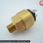
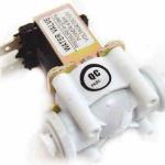
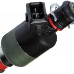
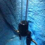
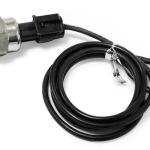
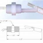
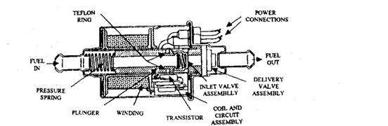
The lift pump on the 6.5 GM Diesel and any other vehicle that uses this kind of lift pump has a defective designed pump on it. it is NOT an electric fuel pump - it is an electrically energized mechanical fuel pump driven by SPRING pressure. Yes SPRING pressure and it is not even an electric fuel pump - meaning it does not pump fuel by electric means or a motor.
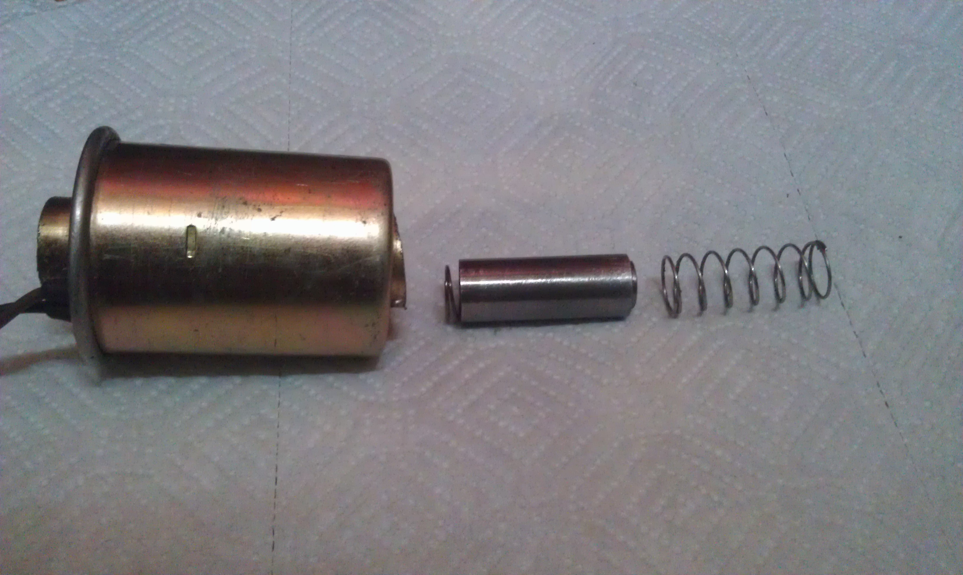
This pump was first introduced in 1981 as a diesel transfer pump. Subsequently it has been modified to make it suitable also for pumping petrol and other fuels. The measure of modifications are introduction of a more powerful coil, a special magnetic steel piston to improve its stroking and a teflon piston ring. The AC UES pump has few moving parts, which DO wear out - and quickly - namely the spring and / or the one-way valve. It can operate at high temperatures, is quiet, and reliable - but its pumping ability as to produce any measurably needed pressure weakens very fast over time - depending on how good of quality the spring is. . The fuel inside the pump is confined to a central tubular core, so the coil assembly and electronic components around it are kept dry.
During the operation of the pump the coil is energized, which pulls the piston down against the resistance offered by the return spring. At the same time, the outlet valve in the delivery port closes, and the inlet valve in the piston crown opens. As the piston moves downwards, (to the left) fuel enters the chamber above it. The electronic system switches off the current to the coil, when the piston reaches the bottom of the stroke. The return stroke of the piston is powered by its spring, forcing the fuel above it up through the outlet valve. This sequence is repeated many times per second. when the spring gets hot or weak - or has poor temper in the first place - its ability to pump fails often within minutes or hours.
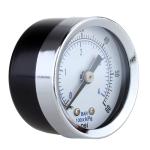
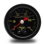
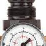
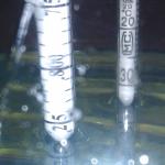
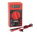
Do not waste your time testing it. It may "test" well - but the real "test" on a GM is if it can hold 5 psi - that means PRESSURE - at idle or wide Open Throttle - which is Stanadyne's standard who designed and built the Injection Pump.
It cannot and by its very design cannot - as no spring can produce 10 to 14 psi doing billions compression and expansion cycles to produce pressure. It si one of the biggest scams in recent automotive history. Now that most all of these pumps are made in Mexico or China and re-branded by companies like Airtex as their own all you get is a pump that immediately fails and you would and do not expect or suspect you bought junk.
A brand new 10-14 psi spec pump after ONE DAY only pushed 3 to 4 psi and while under light to moderate acceleration cn pump it reliably, it is NOT what the IP was designed to operate on.
So . . . even a new pump may produce initially the required pressure and then a few minutes later in driving it will drop to 3 psi.
This is because "springs" are the WORST thing one can do in forming and stressing metal.- they both compress and twist the metal repeatedly and this fatigue actually destroys the characteristics of the metal and the "spring" by design weakens
BRAND NEW pumps have been known to produce "0" psi after 24 hours of operation "new" out of the box - and it is more common than you think - and unless you have a gauge built into your fuel system - or one you can read in the cab - you will never be able to tell.
8 AutoZone "lifetime warranty" CFD0031 (6-9 psi spec) and two CFD0009 (9 to 14 psi spec) pumps all failed repeatedly persistently and almost immediately - and one actually shorted. 3 Airtex e3158 and one Airtex e8153 (same spec as the e3158 with 1/4 NPT fitting instead of the GM "hose bead" fitting for the 6.5 Diesel) failed within 1 week to near "0" psi - and would start at about 6 and as they warmed up dropped to near zero.
If you have driven a 6.5 GM diesel for any length of time you can "feel" it in the accelerator pedal in how the engine responds. The worst thing is - at the same time you are overheating the PMD and the next thing to happen driving on these wek pumps is to blow the transistors in the PMD and - yes that blows the PMD.

It seems now - these days - a lot of these pumps are made in non-US factories and the spring is the key - but the built in check valve in the pump is another point of failure
Bottom line - NO SPRING was ever designed to be put through repetitive high speed continuous compressions intended to respond at the same pressure.
The spring itself heats up and fatigue is constantly introduced into the metal and it is constantly thus weakening. Not one of these solenoid operated pumps can ever last more that a year at spec - and frankly you will see it fail below spec in less than a month
What does this mean ??
It means the IP which operates by multiplying the initial fill pressure - which should be at 5 psi at all times - puts strain on other systems to try to feed the engine properly
The DS-4 pump regulates the fuel pressure by and as it flows through the pump - unlike other "D" series Stanadyne pumps which have the fuel regulated before it enters the pump - and this is double edged sword. It means the IP will try to operate on any fuel pressure and it also means not enough fuel pressure both damages it and results in poor or no performance.
The Stanadyne Operation and Repair manual clearly states the DS-4 is designed for inlet pressure of 5 to 14 psi and will internally and externally return line regulate itself if that pressure range is supplied - and conversely if not - you are asking for unpredictability and trouble.
The best thing actually is follow what Dodge does and use a true motor driven centrifugal lift pump which can put out reliable continuous pressure.
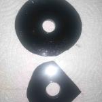
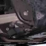
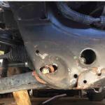
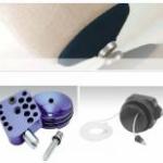
Three things happen to these solenoid lift pumps
1. The spring gets weak - or is manufactured with poor temper - and that stops the full pumping effect
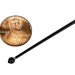
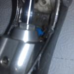
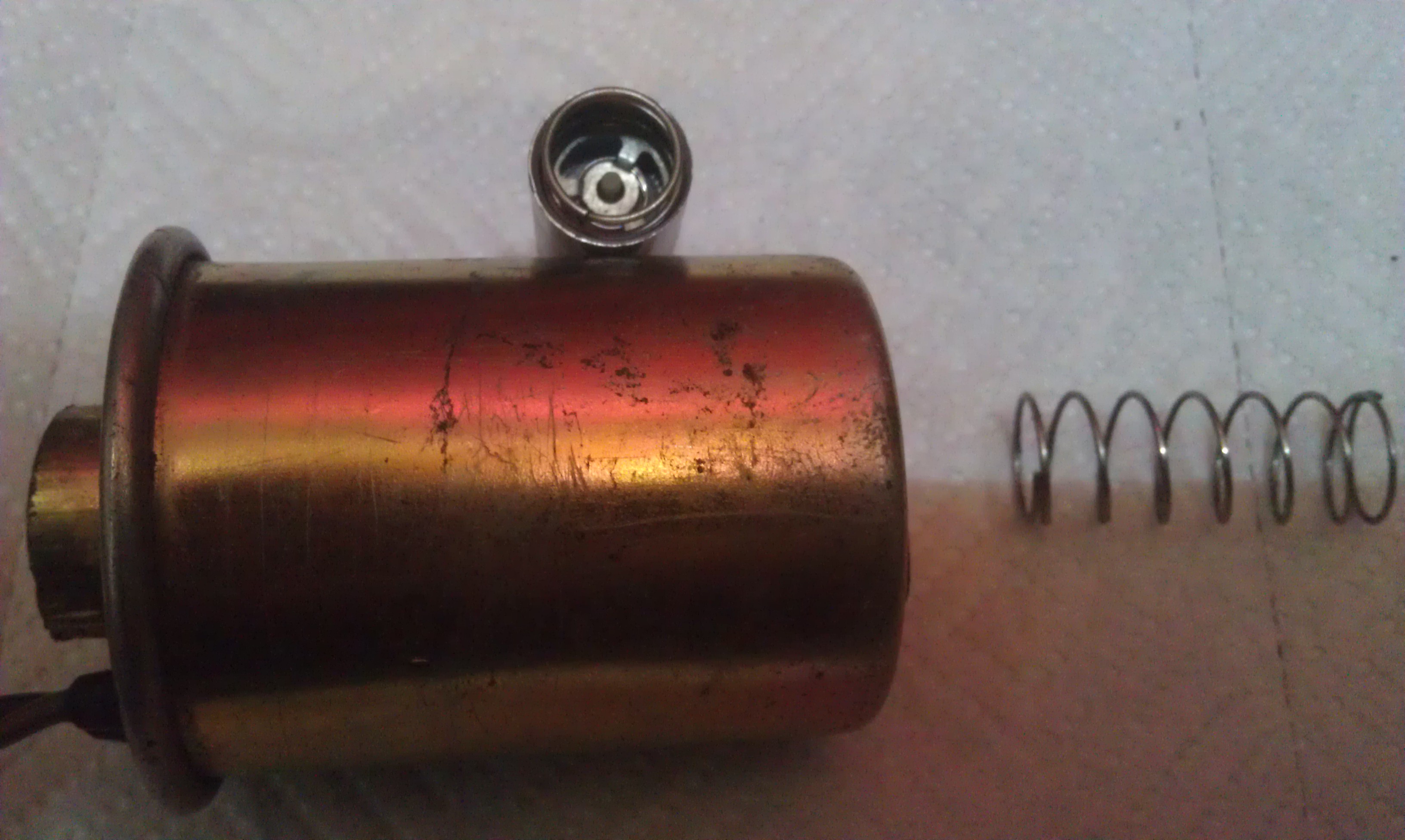
2. The one way valve fails and that stops the full pumping effect - See pic - the valve is inside the piston standing up - and this one could be "blown" through backwards with ordinary human breath - so it was definitely "junk"
3. The piston gets scarred and causes friction which can either draw so much amperage as to blow fuses - which can be caused by low sulfur fuel which lacks lubricity or it could have been manufactured to either too loose or too tight a tolerance - usually the pum is noisy - and in effect this happens over time anyway
In essence these solenoid lift pumps are a crap shoot and are "junk" as a design.
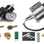
The best thing to do is remove it and replace it with a motor driven true electric fuel pump that can actually push 9 to 14 psi continuously. A Holley "blue or red" style will work, but those pumps are subject to motors drawing high amperage, getting hot, burning up brushes and rotor vane and the relief regulators springs getting weak or failing - or the screw vibrating lose and then it sucks air and will not pump and in general are not a good idea. A rotary vane wet motor style pump line a Carter p4600 (7-9 psi) or p4601hp (14-18 psi) is a much better choice and both have limited lifetime warranties. The p4601HP with its 14 to 18 psi - may cause the 6.5 engine to be 'slightly" harder to start - that is it may stumble upon start up - but normally keeps running and will idle smoothly soon. There are of course cross reference pumps sold by other manufacturers.
Carter says on its website about the rotary vane style pump:
""Originally created for military use, this configuration has been in production longer than any other Carter model. Rotating vanes driven by a heavy-duty wet motor deliver pressure from 4 to 18 psi at a flow rate of up to 100 gallons per hour. This provides excellent lift and prime capability. The pump is available in 6-, 12- and 24-volt versions. It is appropriate for RV, marine, agricultural, industrial and performance applications.""
The "wet motor" is key, as it helps keep the motor cool and have a longer life and run smoother.
The DS-4 has a relief valve that opens at around 10 psi and returns the fuel to the tank and this is good thing for natural fuel cooling - that the IP needs if the PMD is located on the side of the pump - and in fact it is located in the "pool" area which in the inside fills and immerses the optical sensor and then exists at the tope of tip back to the tank. It is in essence a pressure pressure regulator just like a Holley 12-804 and 803 ball opening type fuel pressure regulator is.
Think what happens when a carburetor is starved for fuel - it can only take so much - and likewise if there is too much pressure it floods.
On the GM DS-4 IP system - the engine is monitored by the PCM - computer - which attempts to adjust the IP when it perceives an anomaly.
The most common problematic issue is varying fuel pressure. When fuel pressure drops - the PCM detects a change in horsepower output by the engine sensors and the result is the stepper motor tries to adjust timing to keep the engine running at a specific RPM - and at or near idle -more often than not this is not a successful maneuver both electrically bty the PCM and mechanically by the stepper motor in a timely fashion - and the engine shuts off. This could be due to rising or falling pressure - but often on deceleration rising pressure for a few seconds cause it on a weak pump.
The best performance from a DS-4 IP system would be achieved by a regulated fuel pressure system that can HOLD steady pressure whether at idle or wide open throttle, even though the IP has an internal regulator and fuel return system itself
Why GM did not do this - one can only speculate - but between the emissions issues - and general belief a Diesel fuel injection system is not sensitive to pressure variations resulted in an inferior fuel serving system on the 6.5 - and it has been the root of problems ever since.
The Stanadyne DS4 electronic diesel fuel injection pump has marked it's place in diesel history as a terrible untested experiment done bad in the hands of the driving public . Hundreds of the Injection Pumps were "rebuilt" under the GM warranty service period before GM finally got all the bugs worked out - but at the same tme "gave up" also on the effort planning to replace it with the Duramax as soon as possible.
GM and Stanadyne took a huge gamble when they neglected to do some proper testing on their new system, - and Stanadyne tried to tell them it was an internally regulated and thus fuel pressure sensitive system to fuel starvation - but what GM heard was they could turn down the fell pressure and electronically the PCM / ECM could abd would compensate.
The truth is the DS4 injection pump is actually a pretty solid and reliable unit now MECHANICALLY but the PMD (a.k.a. Fuel Solenoid Driver or aptly the "FSD") is still an issue, because it controls the fuel flow through a fuel solenoid which gets overworked electrically if the unit is starved for fuel. To eliminate hot hard starting and intermittent stalling issues you need to have a minimum of 5 psi at the IP and it can take a maximum of 14 PSI. This is in the Stanadyne service and repair manual for the DS-4 BUT . . . 5 psi is the bare minimum and Stanadyne uses that a test spec number - but that does NOT mean that is what the pump should be fed . . . what the pump should be fed is just under 14 PSI so the re-circulation system is fully working to keep the IP well lubricated with immersion lubrication housing pressure of the fuel oil and fed re-circulated tank COOLED fuel at all times. That is why the IP has the PMD mounted on the side beside a big bath of fuel oil that is supposed to be heading back to the tank at all times. It is for cooling the PMD - but it needs around 10 psi to make sure it is working re-circulatiing fuel oil to take the heat away
For instance the DS-4 is pretty much a self bleeding Injection Pump system IF AND ONLY IF it has adequate head pressure of 5 psi or more at the inlet - and the greater the pressure the easier it self bleeds air out. 10 psi is better and 14 psi is surely great as all the air come tot he top of the housing and is forced out the 10 psi check valve leaving the unit full of FUEL only
While no one will tell you this - as a computer controlled diesel system - it is BEST to STAY AWAY from temptations to "upgrade" and "mod" the DS-4 type systems with manual turbo waste gate actuators and different injector sizes and even larger calibration resistors - because it the engine is not running right - it is a sign SOMETHING ELSE is wrong - and the first place to look is ALWAYS the lift pump. You cannot beat what the computer was programmed to make adjustment to do - you can only make it worse with mods.
The Stanadyne DS4 injection pump is the electronically operated version of the DB2 mechanical pump on early 6.2 Liter GM diesels. It can be finicky if you mix and match different DS4 units with different EPROMS not for the ECM that controls it. It can be hard to troubleshoot also.
The lift pump - is the Achilles Heel of the DS-4 Injection Pump - because FIRST it needs 5 psi MINIMUM at the fuel inlet no matter at start, idle or wide open throttle - or it will operate erratically. (This is the Stanadyne test standard) No matter what you read or see elsewhere - again - it needs 5 psi MINIMUM at the fuel inlet no matter at start, idle or wide open throttle - or it will operate erratically. No flow test in "x" amount of seconds or any other BS you will read - it needs to be 5 PSI MINIMUM at the inlet at ALL TIMES, and you can only measure this by putting an electrical cab mounted gauge in the line - but it is well known that an Airtex E3158 is as well built as a solenoid pump can be and is guaranteed for life with a good quality American made spring that will reliably provide this required pressure. However lately now the E3158 appears is built in Mexico lately and they fail to keep spec pressure not long after install.
These lift pumps are solenoid operated slingshot pumps - the spring provides the pressure and the solenoid only pulls back to release the piston plunger so the spring produces the pressure - and that is why so many get weak and fail so soon - the spring is crap - and that is also why you want a good high lubricity fuel - so the pump has as little resistance in the dry nature of ULSD fuel itself to pumping friction. The solenoid does not produce the pumping pressure. If the lift pump is noisy - it is really near death and is pum[ing likely at a low pressure and volume - and so replace it right away.. It must be said - without a head pressure on the pump - it will likely pump fuel like crazy - but as soon as you close up the line and expect pressure - it will NOT produce it
SECOND, it needs good lubricity fuel because the lift pump needs it to NOT fail prematurely as ULSD fuel is quite "dry" and be able to pump reliably AND the DS-4 is immersion lubricated and needs the 5 PSI to make sure adequate "slippery" oil is forced into all moving parts for lubrication and cooling of the IP and be sure the primary chamber is ALWAYS full of oil to compress to the second stage. This is important because the ECM measures performance using the crank sensor and timing and will adjust the timing and fuel solenoid closure time (also known as C-time) to try to compensate when there is not enough fuel.
It is this second factor - the C-time which is what will lead to a higher duty cycle on the fuel solenoid - which is effectively the "throttle" and higher duty cycles on solenoids cause heat and draw more power - and the next thing that will happen is the Fuel solenoid driver - also known as the PMD - will overheat its power transistors and then either blow one or both of then or blow the 12 volt internal voltage regulator - and the engine will stall - and will not start or start any longer. It will start with a new PMD but the cycle will repeat until you get someway to provide constant relatable fuel to the IP inlet at or over 5 PSI at all times. The IP does have a return valve which opens at 10 PSI so up to 14 PSI will not damage the IP - it will only assure it operates properly.
Here is the sad reality - the higher fuel pressures assure the engine can inject as much fuel as the injectors will allow and it does result in higher emissions - so it is known among those who are in the know - this is reason that GM put a lower pressure lift on the engine until from 1994 to 1999 when they realized that doing so caused the destruction cycle above and many of the IP's were needed to be repaired due to burned up fuel solenoids and / or seized the IP due to not enough fuel pressure for the forced immersion lubrication the IP needed with ULSD "dry" fuel because of this, and they went BACK to an 8 to 12 psi lift ump. The 1992 and 1993 one was a 9 to 14 psi spec pump.
So . . . if you have a 1994 to 1998 6.5 and you have a stock pump or replacement stock lift pump - it is UNDERSIZE and should be replaced with a E158 or EP158 or cross referenced equal output 9 to 14 psi pump. The stock one is 6 to 9 psi and gets real weak fast - and often is found putting out 3 psi or less even a few days after brand new. Of course only three years later the engine went out of service as an option in favor tf the Duramax actually designed and originally built by Isuzu. BUT STILL the best thing to do is replace the solenoid pump with a rotary vane pump -as described above - if is it good enough for Dodge and some Ford diesels - it is good enough to fix the GM 6.5.
This one change will likely end all of your problems and performance will then be something you never knew the engine had. You will feel the accelerator produce power properly.
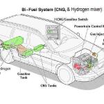
A Diesel engine - and the 6.5 in particular is a good engine to bi-fuel because the electronic DS4 Stanadyne IP working with the PCM on a mechanical injector system is elegant and simple for a Diesel the way GM did it. Some swear at it and try to go around the GM system instead of making the engine run the best it can - and then push the envelope. Others swear by it.
A common mistake pots make is to put in 2250 psi pop injectors on an injection pump which might be weak or setup to pop at 1825 will cause sticking or hammering injectors. System injection pressure to each cylinder is set by the calibration of the injector springs - oem is ~1825 psi min, ~2050-2275 psi max - and when that pressure is reached the injector "pops" open.
OEM injectors when tested "pop" around 1850 - 1900 psi, and one would WANT lower pop instead of higher pop - like with 2250's which are like marine injectors.
1850-1900 psi is the oem auto pop pressure. 2100 psi or 142 bar for 6.5 turbo injectors ,1850 psi or 126 bar for 6.2 and 6.5 naturally aspirated; and 2250 psi or 150 bar for 6.5 turbo "Marine" injectors. Many guys set the 6.5 TD injection pumps to the high end of the pop pressure with the springs +- 5% variation to allow for some pressure drop over time.
There can be simply dirt or other particulate matter in the injector or a pop pressure imbalance of an injector - or bad spray pattern - causing what usually shows up as a sticking loud "hammering" injector, but 2250's might actually causing the problem and not so much the pump
Here is a "for instance" - algae was suspected in the tank and system below the filter which on the van as a center- mount turbo engine is under the drivers seat area just in front of the lift pump. Lve Algae is usually "brown" and dead algae is usually "black"..
It was killed with Bio-Kill and then went to dissolve and push the dead residue to the filter with Diesel Clear. It worked and performance dropped as the filter clogged more. The old filter was removed there were three spares on hand) and changed. change it. Sure enough it was Black inside confirming the suspicions of algae. Most of the black residue was wiped clean and the new filter installed. (You fill the filter with fresh fuel before putting it on to reduce air in the sytem and have fuel ready to hit the Injection Pump) Performance returned, and then an injector started sticking. Obviously some of the algae residue had made its way up the line in the filter change and to an injector.
Gasoline in diesel fuel is a "natural" bio-cide and Algae "dissolver", but ii takes time when mixed with two stroke oil in small amounts as it should be to keep the pump properly lubricated as a Diesel fuel additive.
It took two months of patience - using the fuel additive mix formula - and a bit of erratic engine behavior but finally that small bit of algae worked its way THROUGH the injector - and the engine went back to idling silky smooth and power returned fully - because a sticking or partially clogged injector means also a cylinder misfiring - or dead altogether - and of course "no load rattle" in addition to the "hammering" that comes with it.
That hammering injector shut up finally on its own with no further mechanical intervention. This one of the quirks of the GM 6.5 Diesel system. Another thing many do not realize is that on the trucks - the fuel filter is on top of the engine in the read - and the fuel is effectively being heated before going to the Injection Pump, whereas on the Van - the filter is under the drivers seat area in the underside air flow - effectively cooling the fuel before entering the Injection Pump. There is big deal about PMD relocation for failure due to high heat. Well . . . heated fuel plus low lubricity fuel equals higher heat and greater pump wear faster which - in a pump where only the fuel cools and lubricates it - means PMD failures because the IP gets that much hotter. Vans do not usually have PMD falures - because the air flow past the side manifolds is better and the fuel enters the IP cooler int he first place.
The moral of the story is that lots of things can cause an injector to stick on the 6.5 - or not "pop"- and while your IP may have been "weak" - usually the VOLUME of fuel they can push after pop pressure is what suffers as they wear.
But, also if an injector is partially clogged AND STICKING - AND - you have crappy fuel - it won't light off the fuel cleanly - it will just cause smoke from partial combustion, and you will not know where - which cylinder - easily - it is coming from.
if you have a GM 16015.20-4 - manual or similar; you can read a bit more on the wiring and how the system operates.
If you leave in - or put in a - MAF sensor to report air flow through the engine to the PCM - and do nothing else - then an OBD-II reader like an UltraGauge or DashCommand will use that MAF output from the PCM against the IP fuel duty injection cycle to give you instantaneous real-time mileage readouts.
True a well breathing engine gets the best power development and thus "mileage" for whatever fuel or fuels it is burning - but the beauty of a Diesel as a throttle-less engine - is it can "breath" fuel EASILY by its design. Most do not understand the diesel engine.
A bi-fueled 6.5 GM engine reports horsepower of about 2 to 8 HP at 65 MPH when bi-fueling - because it "THINKS" it is basically idling on diesel fuel - and that is how it can get upwards to 46 MPG of actual mileage of "purchased" fuel - the injection of diesel fuel only acts as a "liquid park plug" only - and for that I WANT low consistent and even pop pressure.
When there is any sticking injector - one could hear serious "no load rattle" in addition to the injector ignition delay hammering noises.
An Intrercooler however is a MUST, and this is partly because the PCM will de-fuel the engine if Intake Air is over 125 F, and boost will not kick in - as the waste gate will be directed to stay more open than closed by the PCM. When the engine first starts - it will go to around 750 RPM - then as it warms and the fuel tends to want to idle the engine faster - the PCM will de-fuel and slowly tank the rpm down to around 640 - until the Intake air is over 80 F and the coolant temperature is over 172 F, then it will reduce it to 600 rpm. You cannot manually adjust idle. There is however manual high idle trigger speeds available of 750, 100 and 1350 rpm for power take-off or high idle for higher alternator output for accessorizes, that can be wired to be triggered by the pCM using a high idle controller - that at least with thye Penn-Tex system cuts off by tapping the brake pedal like cruise control.
The 6.5 G diesel OBD-II engine is a high compression and boosted (turbocharged) perfect platform for other fuels that can develop wild HP and do it cleanly also the industry has been in need of.
Though similar, the OBD-I platform for the 6.5 is dead (pre 1996) and the OBD-II platform for Diesels lives only because it is "still" the OEM and engine standard; however the 6.5 GM is dead in that the Duramax and others are now common rail electronic injection (electronic injectors) direct injection - but the proof of concept as to a Diesel bi-fueling in general remains the same for what bi-fueling can be doing.
We even have a dual PCM type sequential gaseous injection system with metered vapor AND gaseous fuel injection like the GM gasoline is - for the 6.5
As an EPA registered company there is only one way we can market it - and most people are nowhere in the mindset to understand why it is of value or why it must be marketed according to law only; but this and bi-fueling - the future of diesel fueling and engines.
THE INJECTION PUMPS
All the pumps are NOT what you think of as interchangeable AND OBD-I pumps will not always interchange with OBD-II pumps like a 5521 to a 5288.
Here is this example as a "for instance" - is the 5068 pump. it was a 1 year special breed. It was a higher output pump than the 5521 pumps. It had a special EPROM to run it. If you mixed up the EPROM or the pump that was not compatible with the other, all sorts of fun would erupt with idle, and uncontrollable fuel rates. They allegedly only applied to the 94 model year on HD trucks, but they are often confused with other rebuilt pumps and you will not for SURE what EPROM is in any pump. Otherwise the EPROM is the same usually for the 5067/5288/5521 compatible IPs.
For instance a 1994 K2500 L65 vin F truck w/a 4L80E had a DS-5521 pump put in. It suffered hot start issues and the pump was replaced with a DS-5288 and it worked fine then. An L56 engine and L65 engine (also called HD) has a different ECM binary and needs to have different sensors to operate properly and as said above the 5068 EPROM might be in the pump.
When you go mixing and matching the DS4 driven GM 6.5 to other ECM's ANYTHING as an issue could crawl out of the spaghetti to haunt you - not to mention optical sensor and PMD issues and the resistor matters that go with it.
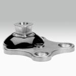
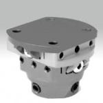
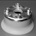
DS4 Injection Pump
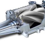
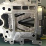
The DS4-831-XXXX Diesel injection pump is a rotary Distributor-type Solenoid-activated 4 pumping-plunger 8 cylinder 0.31" plunger-diameter model - the four remaining digits denote Stanadyne final calibration specs - it is a constant-beginning variable-ending pump design with three modes controlled by the Fuel Solenoid valve: fill - pump - spill
Diesel fuel is the sole lubricant and coolant in the DS4
The IP body and fuel distributor is attached to and rotatable on the engine timing cover and can be positioned within a limited arc wrt 360* and crankshaft Top Dead Center to establish Base injection timing for the fuel distributor - PCM can rotate the internal camring\OS within the limits of the IP body to vary injection timing in a positive direction (advanced) from that Base - the internal fuel distributor rotor, pumping plunger assembly and encoder disk on the IP shaft rotate thru that 360* when the crankshaft spins - the four pumping plunger rollers operate in parallel on the 8 internal ramps on the camring, pumping the 1850psi hi-pressure required to "pop" the injectors during each injection event - the distributor rotor directs the hi-pressure fuel to each cylinder port around the fuel distributor, timed to crank rotation and the piston in each selected cylinder being at some point approaching Top Dead Center - PCM controls the FUEL SOLENOID via the Fuel Solenoid Driver to close the valve that enables the pumping event and opens it to end the injection event - it is a constant-beginning variable-ending pumping\injection event
The oem lift pump is a solid-state electronically-controlled solenoid-actuated shuttle-type fuel pump with two one-way valves - it is pump-thru when failed type - the electronic control regulates pressure according to flow, shutting down at a specified pressure when flow slows, as at idle, resuming pumping as flow increases, as at take-off and driving, but always maintaining the specified pressure - it is called a lift pump because it lifts the fuel from the source tank to the IP, also acting as a transfer pump because it transfers fuel from the source tank to the IP to keep a solid flow and pressure available to the IP
Filtered inlet fuel from the lift pump enters the IP at the top front thru the Engine Shut Off solenoid valve, thru a filter screen into the housing pressure regulator then into the internal transfer pump, which is powerful enough to pull fuel from the tank if the oem lift pump should fail but that is a strain on it - housing pressure is regulated to approximately 25psi at idle by bypassing the lift pump output back into the input, (a tank return line) increasing to upwards of 125psi as engine rpm increases in order to deliver the fuel within the limits set by the ever-narrowing injection window
Not all lift pumps are flow-thru when they fail - those will leave you dead on the side of the road, stranded effectively unable to let fuel be drawn through it.
Now, picture a camshaft, with the lobe ramps rising and falling around the base diameter - comparatively, the CAMRING is a ~2.750" diameter machined collar ~0.75" wide x ~0.425" thick, hardened\ground smooth on the outside diameter surface, with 8 hardened\ground ramps rising and falling around the inside diameter surface, much like an inverted camshaft - the valleys between the ramps, closest to the camring outside diameter, are the base diameter, from where pumping begins - the peaks of the ramps are closest to the physical center of the camring - as the IP shaft rotates, centrifugal force combined with fuel at internal IP housing pressure pushes the pumping plungers outward in their bores against the rollers, forcing the rollers against the camring ramps - the rollers ride inward and outward on the ramps as the IP shaft spins, driving the pumping plungers which intake fresh charge of fuel on the outward stroke, pumping the fuel charge on the inward stroke - the four plungers operate in parallel, pumping into a central chamber, then into the distributor rotor and timed into each of the 8 distributor ports to the cylinders as the crankshaft rotates
A sensor measures this to feed the pulses to the ECM at 1 and 8 pulse intervals
As the pumping plunger roller rides down the camring ramp from outermost plunger position to innermost plunger position, the ECM / PCM closes the Fuel Solenoid (Fsol) valve, allowing fuel pressure to build in the injector pipe connected to the injector until calibrated injector spring pressure is reached, which at that time passes fuel thru the injector nozzle into the cylinder - and the PCM opens the Fuel Solenoid upon reaching the required metered volume (idle to full wide open throttle - fwot), releasing excess fuel and pressure back into the IP reservoir\accumulator, ending the injection event - the rollers reach the ramp peaks and over and down the opposite side of the ramps, heading for the valleys - residual fuel pressure in the injector pipe is prevented from dropping to 0 psi by an external one-way delivery valve at each port on the fuel distributor, thereby reducing pumping time during subsequent injection events for each cylinder - the DS4 (and it's ancestor, the DB2) builds injection pressure for each cylinder individually
The odd shapes of the ~0.250"o.d.\0.093"i.d. injector pipes are resulted from making each pipe the exact same length as the others, such that injection timing is identical for all cylinders
System injection pressure to each cylinder is set by the calibration of the injector springs - oem is ~1825 psi min, ~2050-2275 psi max - when that pressure is reached and the injector "pops", the pumping plunger rollers on the ramps stop building pressure and starts producing volume at that pressure - therefore, injection pressure at any rpm idle to fwot is fixed, only the injected volume is variable - the FSol, under PCM management, meters injected volume.
The PCM manages idle on a per-cylinder basis, measuring angular velocity of the OS timing tracks in the IP to determine if crank is speeding up or slowing down, metering less or more fuel to compensate - this is how idle is maintained under varying loads, such as ac on, turning on the lights, shifting into any gear range from P\N, etc - there is no "fast-idle" like in a gasoline engine (patooie!), which burns unnecessary fuel - therefore, Cylinder Imbalance codes occur only at idle - if Cyl Imbal codes keep occurring after being cleared, the injectors may be sticking, and will require removal for flow-bench testing If the injectors are upgraded, the PCM has no way to compensate for higher-flow injectors, particularly if injector flow rates are not evenly balanced or matched. Usually you will hear this as a "knock" that is actually ignition delay or no load rattle.
DS4 Timing
BASE timing is the most retarded position of the camring / Optic Sensor wrht crank TDC, limited to and set by the physical position of the IP on the timing cover.
ACTUAL timing is the measured position of the camring / OS while the engine is running, and is variable to match rpm and loading requirements
DESIRED timing is the amount of advance with Base that the PCM has determined as required to match rpm and loading requirements
DESIRED and ACTUAL timing should always match within a degree or so
Top Dead Center Offset is a calculated value derived from the total advance available and limited by the physical position of the IP on the timing cover wrt crankshaft TDC - this factor allows a range of rpm and timing not easily manageable in the old mechanical injection systems, where cranking-in advance and turning-up the fuel affected operation across the rpm band, idle to fwot - total available range for TDCO is +2.50* to -2.50*, probably for IP testing\calibration purposes, not useable in-vehicle - PCM will DTC for TDCO over-range at some value greater than -2.02* up to -2.20*
The PCM measures injection timing via the Optic Sensor which is attached to the camring, controlling any required injection advance with the Timing Stepper Motor, which moves the advance piston, rotating the camring / OS - the OS reads timing pulses thru the OS encoder disk attached to the IP driveshaft along with the pumping plunger assembly and fuel distributor rotor - this timing disk, often mistakenly referred to as the tone-wheel, has two separate tracks of timing windows, or slots, circling the disk at separate diameters - (if the Optic Sensor goes bad - you have got real problems.)
The outer-most diameter is the Hi-res track, with 512 slots in 360*, 64\cylinder, a binary number corresponding to available memory locations, used for precision timing determination wrt crank TDC
The inner-most diameter is the lo-res cylinder-timing track with 8 slots, one for each cylinder, which PCM compares to crank TDC to determine start of injection cycle for each cylinder - #1 slot is more than twice wider than the other 7
- 512 / 8 cyl = 64 hi-res slots per cylinder
512 hi-res slots / 360 deg = 1.422 slots\deg or 0.703deg\slot
- #1 lo-res TDC slot is 10 hi-res slots wide to allow for TDCO
10/1.422 = 7.03deg /2 for crank angle
- #2 thru #8 lo-res TDC slots are 4 hi-res slots wide
4/1.422 = 2.817deg /2 for crank angle
The PCM has precise control of the injection event by the 22* rotation of the camring / OS around the encoder disk, which is fixed to the IP shaft which is geared to the camshaft which is timing-chained to the crankshaft - 22* internal advance results in 11* at the crank, as the camshaft-driven IP rotates at 1/2 crankshaft speed
The mysteries of Timing and TDCO - are procedures that can be ONLY performed with a current TECH2:
NOTE: Engine Coolant Temperature is critical, here, as Timing and TDCO procedures do not function if ECT is below ~172*F, although some pcware scantools will command the functions below that limit - TECH2 will not command the functions unless ECT is above ~172*F, which is where PCM is no longer calling for cold-start advance / fast-idle - in cooler climes, Intake Air Temperature also affects cold-start advance and fast-idle, so even if ECT is at 195*F operating temps, if IAT is below ~80*F due to the cold air, the timing procedures will be skewed - if temps are normal and idle rpm is ~695-750 rpm, depending on manual or automatic trans, reliable DS4 timing procedures can be initiated, with repeatable results
+3.5* oem or +8.5* performance Base timing is resulted from the locked-down-by-three-12point-nuts physical position of the IP on the timing cover - remeber the PCM cannot change or alter BASE timing, but can DESIRE timing that is advanced wrt Base timing
When TIME SET is commanded the PCM first sets idle rpm to 1000 rpm to prevent the engine dying during timing procedures, disables DESIRED timing advance, using 0 advance to move the camring / OS to it's most retarded position, then wratchets the TSM to rotate the camring / OS between the physical limits set by the current location of the IP, comparing that range of movement to crank TDC - thus, PCM is determining actual IP position wrt TDC and measuring the available range of advance in degrees at that position - camring / OS rotation is limited to 22* total by the design of the advance piston, which gives 11* total advance at crankshaft - minimum timing position with 0* advance is actual BASE timing, or +3.5*BTDC crank, with total advance at that position of 14.5*BTDC - rotating the IP ~2mm in the advance direction adds +5* for +8.5* actual BASE timing, with max advance of +19.5*BTDC - PCM never commands, and the IP cannot respond to, negative advance, or retard, below actual BASE timing - 'nuther words, it cannot go below actual specified BASE timing value .......unless the IP was mistakenly retarded to some degree less than oem-specified minimum of +3.5*
Once the PCM determines IP position in degrees wrt crank *BTDC during TIMESET, it ratchets the TSM to move the camring / OS into BASE timing position, again, determined by the physical position of the IP - that position is actual BASE timing with 0* desired advance - OBD-I can read this number at any position, OBD-II fudges the +3.5* number at any position in order to fake-out any enquiring minds, in accordance with the FSM blurb on timing alteration resulting in nil performance gains - when TIMESET is exited, PCM resumes normal injection timing operation - now, it is setup do TDCO LEARN
Next, when TDCO LEARN is commanded (and here's where OBD-II KOKO [Key-On - Key Off)] procedure comes from), the PCM once again dials in 1000 rpm, sets DESIRED (advance) to 0 to fully retard the camring / OS for starting position, ratchets the TSM thru min to max timing, verifying what was measured in TIMESET, then moves the camring / OS back to actual BASE timing position with 0 advance - the PCM then computes a TDCO value based on that measured range - now, although the PCM has disabled displayed DESIRED timing function and TSM response in TDCO LEARN, if engine rpm is increased PCM still calls for, or DESIRES, timing advance as required to match the increased rpm - this 'hidden' advance is where the range of TDCO values for each actual base timing setting comes from: PCM continually recalculates TDCO based on the varying advance required for the varying rpm as if that were the actual BASE timing - so, you get a range of values for each actual BASE timing position: at +8.5*BTDC you can get -1.5* to -1.94* to -2.20* TDCO while in TDCO LEARN merely by increasing engine rpm until you see the desired value, then exit TDCO LEARN to lock that value into PCM memory
The KOKO procedure is:
Key On, depress accelerator pedal for not less than 45 seconds, then release - this gives PCM time do do some housekeeping for the coming event
Key Off for not less than 30 seconds - PCM powers down, allowing memory to clear, including,and this is important, any drive-ability parameters
Key On, START the engine - TDCO will re-learn as soon as Engine Coolant Temp and Intake Air Temp come up to operating temps. (172F and 80 F respectivel)
- you may feel the engine hesitate and hear some increased rattle as PCM hunts for Inj Position if timing is way off - may not be any symptom if timing is close
Connect Scantool and note TDCO value in degrees - noting that 1mm movement is about 2.5deg timing change, loosen the nut:
- if less than -0.5deg (more positive) rotate Inj Pump away from turbo-side to increase BTDC timing
- if greater than -1.94deg (more negative) rotate IP towards turbo-side to decrease BTDC timing
Lock the IP down with one nut, do the KoKo thing again - repeat as necessary to get TDCO between -1.54deg and -1.94deg
- you will want TDCO to read above -1.54deg - once it is in that vicinity, then you can adjust TDCO with the scantool by commanding TDCO LEARN, then slowly increase idle till you see the desired value, immediately exiting TDCO LEARN - then recheck TDCO in the monitor-only screen
NOTE: While total available range for TDCO is +2.50* to -2.50*, the PCM will DTC (throw a Diagnostic Trouble Code) between -2.02* to -2.20*, where you must stop, attempt to clear the DTC, then start over from the beginning, as that particular TDCO DTC will seldom clear at this stage - it's a real catch-22, so Beware.
To clear OBD-I DTC's, put a wire jumper into pins A/B in the DLC connector under the dash, turn on the key, push brake and APP to the floor and hold for 1 minute or so. Turn off key, release pedals, then turn on key again. Should have cleared all codes, you should get a flashing 12.
OBD-II requires a scantool or other OBD-II interface to clear DTC's - like an UltraGauge or the DashCommand program
The OBD-II KOKO procedure takes advantage of the positional advance re-measuring (TIMESET) that TDCO LEARN goes thru prior to calculating the correct TDCO value - thus, you don't need TIMESET an OBD-II system.
You also do not need TIMESET in OBD-I unless you move the IP - merely resetting TDCO within each possible range of values for each BASE timing setting can be accomplished with TDCO LEARN, as BASE timing has not been altered
Once again, always do a scan to determine the current parameters before attempting to reset those parameters
NOTE: engine stumble\hesitation will result during the period when PCM ratchets OS timing 22* between minimum and maximum limits to determine IP position - this is normal.
If the Engine Shut Off solenoid is 90* vertical to the horizontal plane across the valve-covers, this should be within a RCH of +3.5* Base timing
A - Stanadyne flow bench procedures for testing the DS4 are not comparably compatible with functional operation required by in-vehicle systems
B - If the EFI values are already correct when doing TIMESET and TDCO LEARN, no change in operation will be observed - if the IP is moved, several things change noticeably, beginning with the 1000 rpm idle which, hopefully, prevents engine dying during incorrectly performed procedures
C - Aftermarket tunes, including chips or eproms, seldom respond like the oem version, particularly in timing functions - don't be surprised if your results are skewed or even non-functional with an after market chip or tune, but alledgedly - the Heath tunes have normal oem functionality with scantools
Standard ser up procedure of replacement 65 DS4 injection Pump
When installing a replacement DS4**, or resetting timing, start with the Engine Shut Off solenoid in 90* vertical to horizontal plane across valve-covers - this should within a RCH of +3.5* Base timing
Start the engine, do an initial scan on engine parameters for 180*F ECT, idle speed 695~750rpm, ACTUAL IP timing +8.5*BTDC, DESIRED IP timing +8.5*BTDC, TDCO -0.5*
ECT must be at operating temperature ~180*F or timing procedures are invalid - I prefer 195*F
Scribe a line across the IP and timing cover flange
Scribe a second line across the timing cover flange, 2mm to the right of the first line - 1mm = 2.5*
Loosen the 3 12pt nuts on the IP flange, rotate the IP, aligning the IP flange line to the 2mm line for a +5* advance, secure the nuts
Start the engine, scan again verifying at least +180*F ECT, ACT\DES +8.5*, idle 695-750rpm
Command TIMESET, rpm will increase, engine will hesitate and stumble as PCM determines new IP position, wait ~5 seconds, exit TIMESET
Command TDCO LEARN, engine rpm will again increase, and hesitate\stumble, will self-exit when new value is learned
Scan again for +8.5*BTDC ACT\DES IP timing, TDCO at -1.5*
NOTE: engine stumble\hesitation is resulted during the period when PCM wratchets OS timing 22* between minimum and maximum limits to determine IP position
----------------------------------------------------------------------------------
If initial scanned TDCO value is elevated to some level greater than -0.5*, this may indicate BASE timing is not +3.5*BTDC
In this case Command TIMESET, exit; command TDCO LEARN, rescan TDCO - if same value, you will have to punt: either
- move IP to exactly vertical and do the standard setup
- or move IP 1mm to right, do TIMESET and TDCO LEARN, scan for new value
repeat at smaller increments until desired TDCO value is attained - PCM will DTC for TDCO over-range at some value greater than -2.02* for OBD1
*Again, aftermarket tunes seldom comply, but TDCO values at idle always represent Base timing, if you interpolate after the initial scan:
-0.5* = +3.5*
-1.5* = +8.5*
----------------------------------------------------------------------------------------
** Alternately, having scribed the line across the IP\timing cover, remove the old IP, accurately measure the position of the scribed line to either end of the upper slot - transfer that dimension to the replacement IP, scribe a line, match that line to the timing cover line when installing the IP, and you should be within a RCH of the original timing, no timing procedures necessary - the IP machining tolerances are that close
OBD-II timing procedures for oem factory tune* - results may vary with aftermarket tunes
- Bill Heath's tunes respond normally to scantools
All DTC's must be cleared prior to performing Timing and TDCO procedures - OBD2 DTC's require a scantool
Comparing procedures using a new TECH2 and Autoenginuity to find no difference, except that an Autoenginuity is more user-friendly
Standard procedure
When installing a replacement DS4**, or resetting timing, start with the Engine Shut Off solenoid in 90* vertical to horizontal plane across valve-covers - this should be within a RCH of +3.5* Base timing
Start the engine, do an initial scan on engine parameters for 180*F ECT, idle speed 695~750rpm, ACTUAL IP timing +8.5*BTDC, DESIRED IP timing +8.5*BTDC, TDCO -0.5*
ECT must be at operating temperature ~180*F or timing procedures are invalid - I prefer 195*F
Do KOKO* to verify timing, rescan, shut the engine off
Scribe a line across the IP and timing cover flange
Scribe a second line across the timing cover flange, 2mm to the right of the first line - 1mm = 2.5*
Loosen the 3 12pt nuts on the IP flange, rotate the IP, aligning the IP flange line to the 2mm line for a +5* advance, secure the nuts
*Do the KOKO procedure
Mash pedal to floor and hold it there
Key ON 45 seconds
Key OFF
Release pedal
Wait 30 seconds
Turn key and start engine after glow cycle
As engine fires up, engine rpm will increase, engine will hesitate and stumble as PCM determines newly-adjusted IP position, then will smooth out to normal idle after new TDCO value is calculated
NOTE: engine stumble\hesitation is resulted during the period when PCM wratchets OS timing 22* between minimum and maximum limits to determine IP position
Scan again verifying at least +180*F ECT, ACT\DES +8.5*, idle 695-750rpm, new TDCO value should be -1.5* to match newly-adjusted +8.5*Base timing
----------------------------------------------------------------------------------
You still need a scantool to verify initial\current\final parameters in OBD2, but timing can be altered simply by using the KOKO procedure, rather than commanding the scantool procedures - TIMESET has been eliminated as an OBD2 procedure, tho you can still use the command - TECH2 has retained the TIMESET command, as the factory scantool is used for both OBD1 and OBD2
----------------------------------------------------------------------------------------
If initial scanned TDCO value is elevated to some level greater than -0.5*, this may indicate BASE timing is not +3.5*BTDC
In this case command TDCO LEARN or KOKO, then rescan TDCO - if same elevated value, or any value other than -0.5*, you will have to punt: either
- move IP to exacty vertical and do the standard setup
- or move IP 1mm to right, do TDCO LEARN or KOKO, scan for new value
repeat at smaller increments until desired TDCO value is attained - PCM will DTC for TDCO over-range at some value over -2.20* in OBD2
*Again, aftermarket tunes seldom comply, but TDCO values at idle always represent Base timing, if you interpolate after the initial scan:
-0.5* = +3.5*
-1.5* = +8.5*
----------------------------------------------------------------------------------------
** Alternately, having scribed the line across the IP\timing cover, remove the old IP, accurately measure the position of the scribed line to either end of the upper slot - transfer that dimension to the replacement IP, scribe a line, match that line to the timing cover line when installing the IP, and you should be within a RCH of the original timing, no timing procedures necessary - the IP machining tolerances are that close
----------------------------------------------------------------------------------------
DEFINITIONS - GLOSSARY OF TERMS DIESEL NERD SPEAK
----------------------------------------------------------------------------------------
Electronic Fuel Injection (EFI) - fuel injection controlled by a computer, with sensors, modules, and solenoids
Common Rail Diesel (CRD) - EFI at super-high pressure, ~20,000psi, injectors are usually solenoids
Analog = infinitely variable signal, voltage can be negative or positive, frequency from DC to LIGHT
Digital = signal is either on or off - signal can be negative going, as from +5v to 0v, or can be positive going, as from 0v to +5v - usually ground-based, 0v, upper level is supply-rail dependent, frequency from DC to Light
Alternating Current (AC) - analog signal crossing a baseline, 0v in AC power circuits, with positive-going and negative-going component - in analog signal circuits, baseline can be shifted to some DC level by the circuitry that generates the signal (output), or reads the signal (input) - usually applied to 60hz ac power generation, positive-going component is equal to negative-going component across the 0v baseline - due to the physical properties of magnets and iron cores, and the electrical properties of copper conductors and coils, ac power voltage generation results in a sine wave, a complex waveform ofsine and cosine calculations which cannot be accurately measured with analog meters or digital meters, so the displayed voltage is not even the RootMean Squared voltage, which would allow calculation of the Peak (and Peak-to-Peak) voltage - high-end DVM's usually have a switchable RMS converter for accurate ac power-line voltage display - it would be switched off when measuring other analog waveforms
Direct Current - unchanging voltage level, like a battery
Thus, we have:
DC - steady voltage state, either polarity, not rising\falling, no frequency component
Analog - infinitely variable, either polarity, can be "alternating", can have frequency component
Digital - steady state, either on or off (ones and zeros), switchable between ones and zeros, can have frequency component
AC - analog, varying with positive and negative voltage content, sinusoidal waveform in power generation, has frequency component - often applied to varying analog signal waveforms without sinusoidal content
In elctronics, Discrete is transistors'n'diodes'n'capacitors'n'resistors'n'tr ansformers'n'fuses'n'stuff - can have discrete digital and discrete analog circuitry
Integrated Circuit (IC) is some of that discrete stuff scrunched together on a teeny silicon circuit board, usually in an *injection-molded epoxy package - can have IC digital and IC analog circuitry
Transistor-Transistor-Logic (TTL) is mostly direct-coupled bipolar transistors with a few-odd diodes thrown in as token representation
Bipolar transistors are NPN or PNP doped junctions, usually silicon but sometimes germanium flavored, are lo-impedance current devices, transfer function results in odd harmonics, single polarity drivers either pull up to the rail, or pull down to 0
Field Effect Transistors (FET) are N or P doped, are hi-impedance voltage devices, operate similar to electron tubes, transfer function results in even harmonics
Complementary Metal Oxide Silicon (CMOS) devices are hi-impedance FET circuits, direct-coupled circuitry is similar to Complementary Output Pair (COP) hi-fi power amps, where N device pulls signal up, P device pulls signal down (and verse vica), very sensitive to static discharge
Metal Oxide Silicon FET's (MOS-FET) are discrete and IC devices, usually for power circuitry, very sensitive to static discharge
Analog is infinitely variable
Analog control is infinitely variable
Digital is on or off
Digital control is on or off
Digital logic is multiple on\off circuits parallel-arranged in binary bits'n'bytes
One form of computer-synthesis is like analog logic
----------------------------------------------------------------------------------------
Sensors
A magnetic pickup sensor with a coil around a magnet will give an analog signal something like a sine-wave when the tooth sweeps by, as in the speed sensor for the speedometer, and the two speed sensors in the 4L80E - those are 2-wire twisted-pair because of the low-voltage ac signal, and go thru an amplifer\squaring circuit in the PCM and VSS module for conversion from analog ac to digital wave suitable for PCM logic circuitry
A Hall-effect device (magnetic-type) sensor sets a digital off till the tooth sweeps by the pickup, then an abrupt rise to on then abruptly back off - it is a square pulse, as from the Crankshaft Position Sensor (and Cam Sensor in gassers (patooie!)) - this type sensor has 3-wires, one for +5v power, one for ground, and one for digital signal to PCM logic circuitry (PCM is +12v powered, but has internal +5v regulators for logic and sensor reference)
In an Optic Sensor a similar square on-off pulse occurs when the encoder-disk window sweeps between the Infra-Red diode transmitter and the IR-sensitive photo-transistor receiver - this type sensor will usually have 3-4-wires, +5v power for the diode, ground for the diode and transistor, digital signal output
A varying frequency creates a varying voltage which drives a meter to indicate varying crankshaft rpm - the analog tachometer in these trucks operates off one phase of the 3-phase winding in the alternator, which is a variable-frequency 3ph ac generator with solid-state rectifier diodes and 400hz regulator
The speedometer works similar, but with varying freqency from a sensor on the transmission or transfer case output shaft
----------------------------------------------------------------------------------------
PCM signals
PCM has a 12.5mhz clock with 512k eprom, receives signals from several sensors, analog signals into op-amp circuitry, digital signals into digital circuitry, and sends digital control signals to several solenoids and modules - 6.5 PCM does not do any analog control
A digitally-synthesized signal is how a digital computer with ones'n'zeros can make a varying analog signal - similar to the on-screen display of curves on the old b-w, cga, vga monitors, which was a series of digital steps that formed coarse curves and circles - the more and finer the digital steps the smoother the curve
The 6.5 EFI PCM is too primitive for computer synthesis - the nearest thing to c\s in these trucks is the stereo\cd\dvd\mp3\serious radio - also the radar detector - then a cell phone - blackberry - pacemaker - XBox - Wii - Buck Rogers space toy.................
Here are the modules, sensors, solenoids, and signal-types used by the PCM - passive sensors are part of a 'nuther separate circuit, do not generate output without external influence - active sensors are solid-state devices requiring power and ground to generate a signal on a third wire:
IAT, ECT sensors (to PCM) are passive temperature-variable resistors in a +5v ref voltage-divider circuit in the PCM - an analog-to-digital converter in PCM changes the variable analog voltage to 16-bit binary digital 1-2-4-8 1-2-4-8 1-2-4-8 1-2-4-8
Boost and EGR sensors (to PCM) are active analog-voltage pressure transducers using +5v ref from PCM - the analog voltage varies as pressure changes - an analog-to-digital converter in PCM changes the variable analog voltage to 16-bit binary digital
Crank Position Sensor, Optic Sensor are active - pulses increase as rpm increases - to PCM:
5v_ ''''''''''''''''''''__ ''''''''''''''''''''''''''' __ '''''''''''''''''''''
0v_________| |___________| |________
NOTE: PCM can use clock ticks to turn on electronic switches for any length of time, as below:
5v_ ''''''''''''''''''' __ '''''''''''''''''''''''''''' ______ '''''''''''''''''''''
0v_________|||___________||||||||________
Wastegate Solenoid drive, pulse width modulated - WG duty cycle runs ~66%, decreasing to reduce Boost, increasing to raise Boost - also EGR solenoids -from PCM:
~10%duty cycle
12v_____''''''_ ''''''''''''''''''''''''''''''_''''''''''''''''''''''
0v________||___________||_________
~50% duty cycle
12v_____''''''_____ ''''''''''''''''''''_____ '''''''''''
0v________|||||||_______|||||||____
~100% duty cycle
12v_____''''''_______________________
0v________|||||||||||||||||||||||||||
Fuel Inject signal from PCM to FSD module - pulse width increases to increase fuel rate - (Note:any of these three signal examples may be inverted - I've slept some since '03\'04) :
5v_ ''''''''''''''''''''__ ''''''''''''''''''''''''''' __ '''''''''''''''''''''
0v_________| |___________| |________
Fuel Solenoid Driver module to FS coil - pulse width increases to increase fuel rate - from PCM:
Idle
12v___''''''''''''''''''''''''''__ ''''''''''''''''''''''''''' __ '''''''''''''''''''''
0v______ _______| |___________| |________
FWOT
12v___ '''''''''''''''''''''''''____________ '''''''' __________
0v_____ ________|..................|___|
:
Timing Stepper Motor drive, 2 phase - each pulse steps motor ~5* - TSM reverses direction when lower signal leads upper signal - from PCM:
5v_____''''''____'''''''''''____'''''''''''''____
0v_______|.....|___|.....|____|.....|_____
5v_______''''''''''''____'''''''''''''____'''''''' '''''____
0v___________|.....|____|.....|____|.....|_____
VSS (to PCM) after analog input from magnetic pickup has been squared - output frequency varies with vehicle speed - mag pickup is passive, becoming 'active' as "tone-wheel" tooth approaches sensor: a real conundrum :
5v_____ ''''_'''''''_''''''_''''''_''''''_'''''''_''''''_' ''''''_''''''_
0v_____ _| |_| |_| |_| |_| |_| |_| |_| |_| |
Speedo, Tach drive from VSS, PCM - active - frequency varies with vehicle speed and engine rpm - to speedo, tach:
5v_____ ''''_'''''''_''''''_''''''_''''''_'''''''_''''''_' ''''''_''''''_
0v_____ _| |_| |_| |_| |_| |_| |_| |_| |_| |
4L80E = PCM uses pwm at ~30hz to apply TCC clutch, PCM uses prm to vary line pressure
----------------------------------------------------------------------------------------
8888888888888888888888888888888888888888888888888888888888888888888888888888
On-going collation -
Cranking the engine CAUSES THE PUMPING PLUNGERS TO MOVE IN THEIR BORES IN THE ROTOR, PUSHING FUEL INTO THE CENTRAL ROTOR PASSAGE TOWARDS THE OPEN FS METERING VALVE WHICH IS SPILLING THE FUEL, PREVENTING ANY PRESSURE RISE UNTIL PCM FIRES THE FSD TO CLOSE THE VALVE)
And that fuel, if PMD were dead, would only go through the valve because FS METERING VALVE) would be forever open? = (CORRECT) How does the open valve prevent the fuel from being "distributed" to injectors. = ( FUEL SPILLED BY THE OPEN METERING VALVE CANNOT GO THRU THE SELECTED PORT TO THE INJECTOR - VALVE CLOSES, SEALING ROTOR PASSAGE FROM SPILL CHAMBER, FUEL IN ROTOR PASSAGE GOES TO SELECTED DISTRIBUTOR PASSAGE - PRESSURE RISES THRU SELECTED PORT TO INJECTOR)
the plunger is IN ROTOR PUMP BLOCK) and valve is in the (ROTOR - spill chamber is IN THE DISTRIBUTOR - END OF ROTOR AND METERING VALVE is in THE SPILL CHAMBER IN THE DISTRIBUTOR, MINUS FS SOLENOID, ARMATURE, AND ONE-WAY PORT VALVES -THAT SPRING-LOADED ROD OPENS THE VALVE WHEN FS DRIVE-CURRENT IS REMOVED - METERING VALVE OPENS THE ROTOR PASSAGE TO THE SPILL CHAMBER, FUEL PASSES BACK THRU TO THE PUMPING PLUNGERS - ADDITIONAL FUEL AT HOUSING PRESSURE ENTERS THE PLUNGERS THRU THE CHARGING ANNULUS PASSAGE IN THE DISTRIBUTOR HEAD)
How does fuel injection change at constant pulse width = (CLOSURE DURATION IS CONSTANT, hopefully - HOLDING\METERING PULSE WIDTH IS VARIABLE PER DEMAND). Does the valve have to fully seat to begin injection? = (MUST BE FULLY SEATED TO BEGIN PUMPING\PRESSURE RISE WHICH POPS INJECTOR - PUMPING\INJECTION EVENT BEGINS WHEN PCM RECEIVES FS CLOSURE SIGNAL, INDICATING VALVE IS FULLY SEATED - PCM OPENS VALVE TO END INJECTION, SPILLING REMAINDER OF FUEL MOVED AS ROLLERS HEAD UP REMAINDER OF RAMPS TO THE PEAKS - THEN OVER TO THE DOWN-RAMPS TOWARD THE VALLEYS TO BEGIN AGAIN)
----------------------------------------------------------------------------------------
that is the fuel metering valve, of which one inherent function is spill
GMTDScan is a GREAT pcware scantool, for OBD-I 1994 AND 1995 but that and a DVM does not tell the whole story - Closure Time pulse from the FSD module tells the PCM to start timing the metering pulse, which varies in width according to demand fuel rate - overall pw timing includes CT
LIMP MODE fixes idle rpm, locks TSM timing, limits max fuel rate by limiting the metering pulse width, locks out turbo management, locks out Cruise, limits the 4L80E to two lower ranges - this results when CPS or OS failure occurs, CT is too long or erratic\intermittent, etc - these limitations resutts in long-start condition, requiring long cranking periods before engine will fire
Secondary "limp modes" occur when certain parameters are exceeded, such as high Boost, where PCM will set DTC, reducing and limiting fuel rate and limiting turbo control until restart - however, PCM is too primitive to reduce fuel rate when Boost is too low for demand conditions, thus the black smoke with reduced power when wg system fails - that scenario is not a limp mode
This is all digital, based on the 'clock' pulses from the OS on the 512-slot track on the encoder disk, and sync'ed by the clock pulses from the 8-slot cylinder track and the CPS - PCM has 64 counts per cylinder with which to work it's magic - the 64 counts are spread across TDC of each cylinder, some BTDC, some ATDC, allowing precise management of the injection\combustion event
Any perceived "voltage variation" is due to frequency and ELI - however, low battery voltage at the FSD, be it from grounding, resistive connection, or failing battery system, will increase CT due to slower FS reaction time, thus affecting injection event timing - DTC36: there's ole ELI, at it again................
----------------------------------------------------------------------------------------
Remember, in digital signals, the signal is driven to the upper rail, in this case 5v, but is also driven to the lower rail, 0v, so DVM must integrate and average the upper voltage with 0v - you will get different readings in DCV and ACV ranges
An oscilloscope is the desirable tool for investigating computer-controlled systems, as most everything is digital: solenoids, valves, switches, position sensors, etc - temperature and pressure sensors are mostly analog, with variable resistance and variable voltages representing response to change - these can be read with a 'scope or DVM
With inductors in the system, inductive kick may be a usable part of the signal, but not even seen by a DVM - inductive kick can be as high as 2400v in a 12v system - the FS coil gives between 100-180v of inductive kick when power is applied, which is why the PNP driver transistors are hi-voltage rated, in addition to hi-current rated, designed to pass a lot of current thru the FS coil
The waveform at question * resembles the Fuel Injection Pulse Width at idle, and at question ** resembles the waveform at FWOT, but on a much higher voltage, as the drive voltage is just under +12v battery voltage due to solid state forward voltage drop of the bipolar drivers and the steering diode in the emitter circuits - on-time to off-time is determined by demand fuel rate - the max pulse width is never as wide as the duration for the rollers to ride completely up the ramps
----------------------------------------------------------------------------------------
The PCM sends a digital Fuel Inject control pulse to the FSD, which is (a) a power driver that applies battery current to the FS solenoid coil via the collectors of the paralleled PNP driver transistors, and (b) a comparator circuit that monitors that current for the changes that result when the flux density changes as armature\plunger begins moving, continues forward motion, and stops as the valve seats - the resultant digital Closure-Time pulse is sent to PCM which starts counting clock ticks for injection pulse width timing - PCM has been counting ticks since sending the injection pulse to the FSD, so CT is included in Injection Pulse Width timing - FS is merely a coil, responding to applied power - power on is a 1, coil energized, power off is a 0, coil de-energized
So, let's talk a little bit about Limp Mode - and just fyi, kiddies: Sildenafil citrate won't even help here...........
To wit: the much-dreaded oft-feared Limp Mode, or, more formally, Limp Home Mode, is resulted when PCM senses over-limit, under-limit, intermittent or erratic response from, or loss of, a sensor(s) - symptoms are CEL, very obvious loss of power, limited APP input, 1st and shift to 3rd gear only, no turbo, no TCC lockup, no cruise, no nuttin' - but the engine will get you to a desired destination, albeit, not in the style to which you have become accustomed
tbc..............
Basic 6.2\6.5 engine timing, crankshaft to camshaft, camshaft to IP, courtesy of MATUVA and MGW:
| Attachment | Size |
|---|---|
| how_lift_pump.jpg | 898.24 KB |
| one_way_valve.jpg | 787.2 KB |
| solenoid_lift_pump.jpg | 28.86 KB |
| disgust.jpg | 44.23 KB |
| prechamber.jpg | 72.21 KB |